0
\$\begingroup\$

I am wanting to control 5 voltage signals with MOSFETs (0-1V each, through drain-source of each MOSFET) from BNC connectors to then observe with an oscilloscope. The circuit is optically isolated and activated by a transistor on the 12V VCC line. The basic circuit
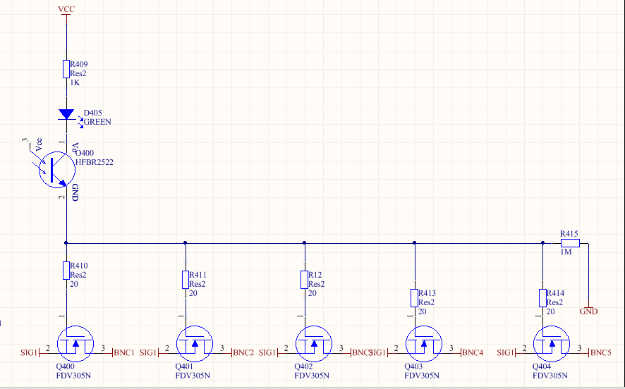
I have a few questions about the feasibility of this due to my basic knowledge; 1) Is it actually okay to connect MOSFETS like this, will they operate correctly/simultaneously or will the small voltage signal not flow?

2) I understand that the capacitance of the MOSFETS will slow down the switching, how do you calculate this effect?

3)Is 12V enough to switch all of the MOSFETS?

4)Are the pull down/gate resistances appropriate?

Please note I am very new to circuit design/electronics, any direction on this would be much appreciated.

The MOSFET I have available to me; http://www.mouser.com/ds/2/149/FDV305N-888896.pdf but can change it very easily The optical transistor; http://datasheet.octopart.com/HFBR-2522-Avago-datasheet-7278264.pdf

\$\endgroup\$
2
  • \$\begingroup\$ Is there a reason why you don't use a CMOS bilateral switch IC like the venerable 4066 for this? \$\endgroup\$ Commented Dec 5, 2017 at 23:15
  • \$\begingroup\$ I can see lots of reasons why this can never work. How do you prevent Vce of Rx from saturating due to gate charge and IcRc+Vf drop and only 1M to pull it out of saturation. I see no reason for ganged gate charged low RdsON switches with only 1M gate to emitter bias to 0V. You dont have any bandwidth and you lose voltage gain with emitter follower and have no load resistance. No design merits are obvious to me. worse yet, no specs. Although obsolete, try to mimic test setup in datasheet \$\endgroup\$
    – D.A.S.
    Commented Dec 5, 2017 at 23:44

1 Answer 1

1
\$\begingroup\$
  1. a) For yor stated purpose, experimenting, yes it is ok. b) They will be roughly synchronized. Whether they will turn on depends on where the source is connected. According to the datasheet these MOSFETs start turning on around 2.5 V, and since they're N channel MOSFETs, this means 2.5 V between gate and source. So if the source is connected to GND, then 12 V should be ample. If the source is floating, or connected to a high impedance oscilloscope probe, or anywhere that is not at a voltage potential that is at least 2.5 V lower than the gate, you can not expect them to turn on. But if you connect the sources to ground, they will definitely turn on.
  2. You can think of the gate as a capacitor between the gate and source terminals. Google charging a capacitor. That should tell you much of what you want to know about charging a MOSFET gate.
  3. 12 V gate to source seems to be the absolute maximum rating for the MOSFETs in your schematic. In practice this means that 12 V is too much for them to handle in the long run. However, the LED probably drops a couple of volts, and the optical transistor will drops a little bit of voltage as well, so that should make the MOSFETs able to survive your experiments. (Assuming that the source is connected to GND.)
  4. The approprieteness of the pull-down depends on how fast you want the MOSFETs to switch, but 1 megaohm seems a tad high. The LED will probably not light up at that current. Use Ohm's law with 1M and 12V, see what current you get. I would probably go for somewhere between 10 and 100 kOhm (and still not expect the LED to be particularly bright).

As Trevor pointed out in the comment, the voltage potentials and/or signals that the source and drain are connected are relevant. As this was lacking in the schematic, I made some ASSumptions. I hope that my latest revision to this answer has salvaged it, though.

N-channel MOSFETs are usually used as "low side switches" for this reason. This means that the source is connected to ground, and whatever load the MOSFET is switching is connected to drain - in other words, the load and the MOSFET form a variable voltage divider with the load on the "high side" and the MOSFET on the "low side".

If you instead want to connect the load to the source, in other words use a MOSFET as a high side switch, a P-channel MOSFET is usually the more appropriate choice.

\$\endgroup\$
1
  • 1
    \$\begingroup\$ I would not be so sure... It depends on where SIG is going to. It it's going to a high impedance scope terminal as he has indicated, the things will never turn on. MOSFETS are also not great at blocking high frequency AC signals. \$\endgroup\$
    – Trevor_G
    Commented Dec 5, 2017 at 21:52

Your Answer

By clicking “Post Your Answer”, you agree to our terms of service and acknowledge you have read our privacy policy.

Not the answer you're looking for? Browse other questions tagged or ask your own question.