1
\$\begingroup\$

This is really a followup to a previous question to provide an updated schematic and photograph at the request of a commenter on that question. I'm not sure if there is a better way to provide such an update to a question but here it is anyway...

I have the following circuit:
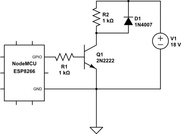
schematic

simulate this circuit – Schematic created using CircuitLab

When I measure the voltage across R2 I don't see the 18V being supplied into the collector of transistor scaling linearly with the value of the PWM GPIO of the NodeMCU. It ranges from 9.35V with the GPIO at 0 (i.e. off) and 17.14V with the GPIO at 1023 (on "full"). With a GPIO value of 512 it reads 13.16V.

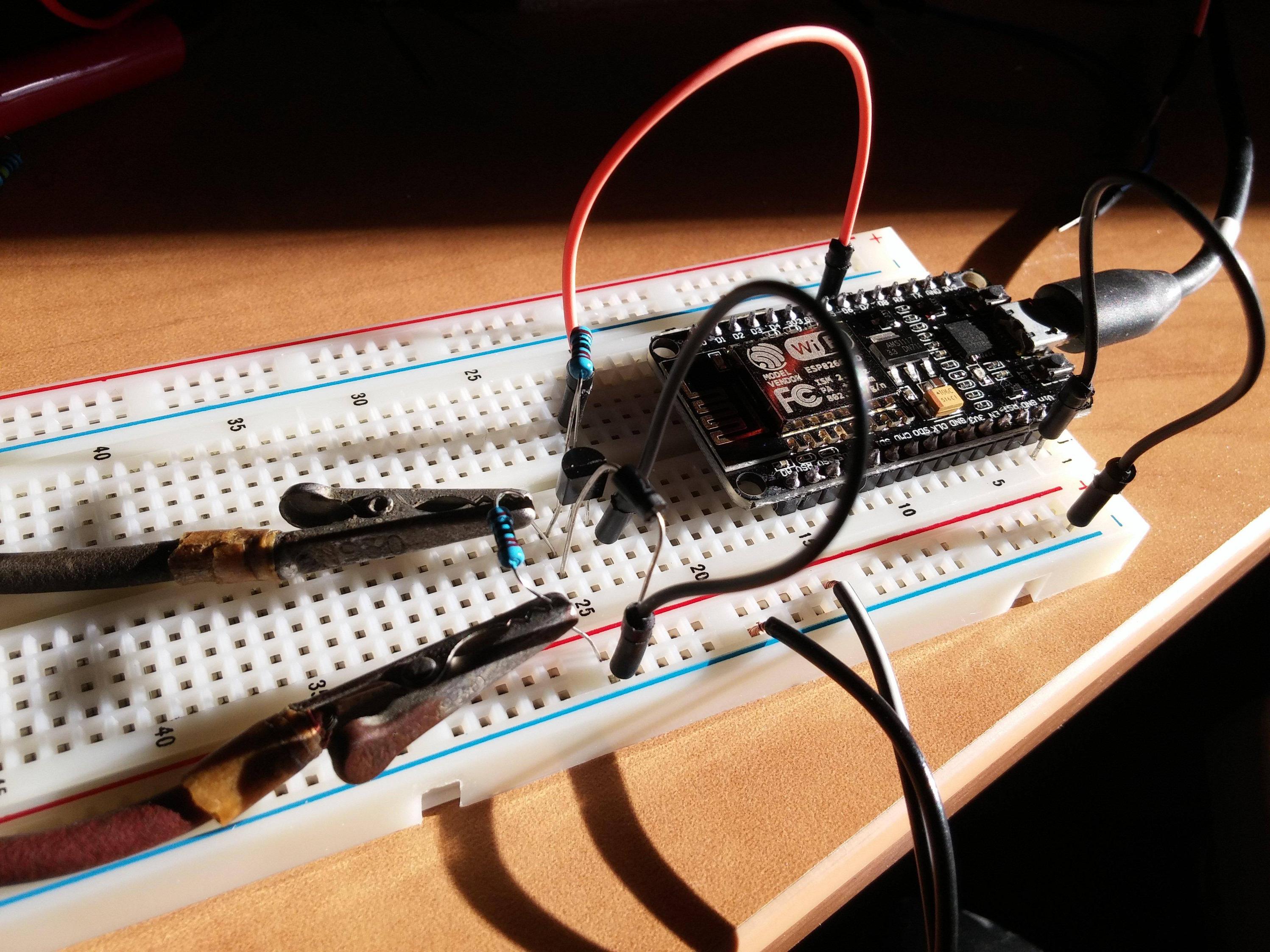
I tried my best a photograph of my set up:

enter image description here

About the only thing that is not clear in the photo I think is that the resistor "above" the transistor is between the GPIO with an orange wire and connects to the base (middle pin) of the transistor.

\$\endgroup\$
1
  • \$\begingroup\$ downvote for knowingly posting a duplicate question. the better way is to edit the original question. \$\endgroup\$
    – jsotola
    Commented Dec 26, 2017 at 20:02

2 Answers 2

7
\$\begingroup\$

The correct way was to edit your previous question but we're all here now ...

enter image description here

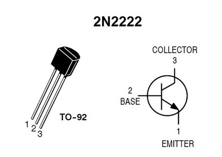
Figure 1. 2N2222 pinout.

enter image description here

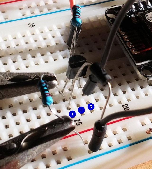
Figure 2. You have the collector resistor connected to the emitter at (1). The base looks OK at (2). You have the collector grounded at (3).

Swap the emitter and collector wiring by turning the transistor 180°.

\$\endgroup\$
3
  • \$\begingroup\$ +1 Yup that would do it... Lucky the gpio did not blow. \$\endgroup\$
    – Trevor_G
    Commented Dec 26, 2017 at 19:43
  • \$\begingroup\$ Yes, this was exactly the problem. I should have double checked better. Now things seem to be working as expected. Much thanks for the pointer. As an aside, I didn't edit my previous question about this since it seemed like it would be changing history and would make existing comments that were based on the pre-edit question no longer relevant. I could imagine coming across such a question that had been edited and trying to make sense of pre-edit comments against the post-edit question. In any case, if that's how things are done here, I will keep that in mind in the future. Thanks again. \$\endgroup\$
    – Brian
    Commented Dec 27, 2017 at 12:42
  • \$\begingroup\$ Full marks for having the wit not to make the original answers seem irrelevant. The usual technique is to add a horizontal rule at the bottom of the original post and mark the remainder as 'Edit 1' or 'Update'. It's not good if a question evolves so much that it's almost unrelated to the original but sometimes it is necessary particularly when you're learning the terminology or basic concepts. +1. Don't forget to accept one of the answers and upvote as many as you found helpful. \$\endgroup\$
    – Transistor
    Commented Dec 27, 2017 at 13:12
2
\$\begingroup\$

The transistor is broken, or it is not hooked up according to the schematic you provided.

With 0 V on the left end of R1, the transistor should be fully off. That means there is no current thru R2, so the voltage at both its ends is the same, so the voltage at the collector should be 18 V.

When the GPIO is about a volt or higher, the transistor should be on full enough to saturate. In that case the collector should be at around 200 mV.

If these two things aren't happening, then something is wrong. The most likely issue is that the transistor is blown from previous mis-experiments. Try a new one.

Also make sure you have everything hooked up right.

I just looked at your picture, and something doesn't seem right. I didn't look up the pinout of a 2N2222, but I thought those had the usual E-B-C pinout left to right with the flat towards you and the pins down. I can see one end of the diode connected to the left leg. If my pinout recollection is right, then that's the emitter. Neither side of the diode should be connected to the emitter. Check the datasheet for the pinout.

\$\endgroup\$
1
  • 2
    \$\begingroup\$ Whoever downvoted this, please explain what you think is wrong. From the answer by Transistor, it seems that my suspicion stated in the last paragraph was in fact the problem. The remaining information still seems correct to me. \$\endgroup\$ Commented Dec 26, 2017 at 18:57

Your Answer

By clicking “Post Your Answer”, you agree to our terms of service and acknowledge you have read our privacy policy.

Not the answer you're looking for? Browse other questions tagged or ask your own question.