I'm currently attending a course on "experimental problem solving" and we just started talking about TDR (time domain reflectometry). I do understand that reflections occur whenever there is a change of impedance, and that you can terminate them by making sure the load resistance is equal to the impedance of the cable. However, we now got a question to explain why we get reflections in a "T-intersection" (not sure about the real name but basically a dongle to connect three cables together) even though we match the load resistance with each of the cables impedances. Can someone explain why this happens, or some source where you can read about these things?
-
\$\begingroup\$ A cable terminated by R at both ends then intersected in the middle will see R/2 \$\endgroup\$– D.A.S.Commented Jan 25, 2018 at 20:39
-
\$\begingroup\$ @TonyStewart.EEsince'75 How come? Can you just view the resistors as parallel and sum their conductances? For me, it still seems like the signal has to pass through the two cables separately, each with their resistance of their own that needs to be terminated to avoid reflections. \$\endgroup\$– EstrozixCommented Jan 25, 2018 at 21:04
-
\$\begingroup\$ you may use any source impedance, apply any signal and measure the response in any way (TDR, DMM, SA, NA ) and come to the same conclusion . I only suggested the obvious intuitive example. \$\endgroup\$– D.A.S.Commented Jan 26, 2018 at 0:19
-
\$\begingroup\$ The differential equations for telegraph equations might assist understanding. Lord Kelvin became famous for this work, making the English military able to communicate around the world via cable, thus sending ships where needed. \$\endgroup\$– analogsystemsrfCommented Jan 26, 2018 at 5:16
2 Answers
As you know, when you apply a (matched) voltage source step function to a transmission line you will instantaneously see the characteristic impedance \$R_C\$ of the transmission line. So the current that voltage source needs to drive will be \$\frac{V_{in}}{2R_C}\$ (\$2R_C\$ for the matched series resistor + the characteristic impedance of the transmission line) and the voltage at the input of the transmission line will be \$\frac{V_{in}}{2}\$.
The waveform of the step function will propagate through the transmission line, not really "seeing" what's in front of it. At a certain moment, the signal will encounter the T-section. At this point, the wave will "see" a characteristic impedance for two transmission lines in parallel (\$\frac{R_C}{2}\$).
This change in impedance will create a backward wave to "ask" more current to drive the lower parallel resistance. This causes a backward wave (pulling the voltage in the transmission line lower). After traveling all the way back to the voltage source, that source will suddenly have to drive the larger current (\$\frac{2V_{in}}{3R_C}\$). The voltage at the input of the transmission line will also suddenly have dropped (\$\frac{V_{in}}{3}\$).
As the source is matched, no new forward wave is created. The backward wave didn't see a change in impedance after all.
However, we now got a question to explain why we get reflections in a "T-intersection" even though we match the load resistance with each of the cables impedances.
Ignore the load and just think about the two cables joining at the "T" intersection. If both cables are 50 ohm then there is no problem - matching is perfect. However, when you add the load you are putting an extra 50 ohm in parallel with the previously joined and matched cables. This creates a reflection.
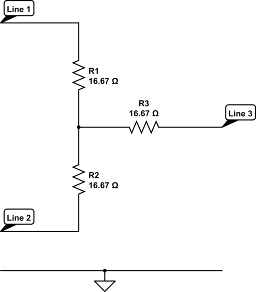
If you wished to join three cables of impedance/source 50 ohms together, the intersection would need three 16.67 ohm resistors to avoid reflections like this: -

simulate this circuit – Schematic created using CircuitLab
It's fairly easy to work out.
