0
\$\begingroup\$

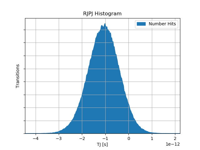
I made some jitter measurements of my high speed serial link yesterday. Now i'm analysing the jitter sources, and found out, my random jitter is often not around zero, most time about -1 .. -0.5ps.

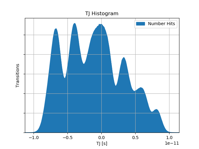
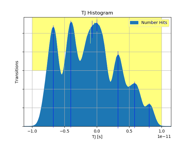
What's the reason for a not 0 mean of the random jitter? RJPJ Histogram TJ Histogram The pictures show a plot of the random/periodic jitter and the total jitter. The scope cannot give a seperate plot for random jitter and periodic jitter, but the second should be similar to a dual dirac function, so symetric around 0. So why is my RJPJ not around 0?
The TJ is a convolution from RJPJ with Data dependend Jitter(DDJ). DDJ is caused from a PRBS-7.

Edit: I am measuring differential transceiver of a fpga, connected by two skew matched cables. There is no "known" asymmetry in my measurement. If this would be static asymmetry, every measurement would have been an equal RJ, i think. I have a 16Gbit/s NRZ signal, the cables are rated up to 18Ghz, the connectors on the Board 12GHz.

\$\endgroup\$

1 Answer 1

1
\$\begingroup\$

A non-zero mean implies your sync clock has a constant phase offset error. from some source. ( computation error? mixer error?) enter image description here

Bit edge-shift can be caused by many things:

  • Pattern dependent bit shift, assymetry f/BW ratio
  • Non-linear phase shift or non-flat group delay in the passband of the channel
  • asymmetry in the data pattern
  • aliasing in the measurement system with data rate
  • path length echos from return loss.
  • logic skew in prop delay
  • non-sine or non-random noise in clock PS
  • etc.

Can you elaborate on the system parameters and tests variables?

You can report back on which were relevant or which items you can control by changing each variable and create budget of jitter for each source in order to improve BER or Bit rate.

\$\endgroup\$
11
  • \$\begingroup\$ Sorry if i was unclear: I was asking about the non zero mean of my random jitterl, so this should not be affected from ISI or pattern. \$\endgroup\$ Commented Mar 1, 2018 at 9:47
  • \$\begingroup\$ yes it can if ISI is non symmetrical . try different patterns (RLL?) and find worst case, best case \$\endgroup\$
    – D.A.S.
    Commented Mar 1, 2018 at 9:52
  • \$\begingroup\$ The mesurement system must not be synchronous to data rate. Change cable length to see if return loss shifts some of the peaks. Precompensate your tx data. I just suggest things to check.. You can report back on which were relevant \$\endgroup\$
    – D.A.S.
    Commented Mar 1, 2018 at 10:06
  • \$\begingroup\$ A non-zero mean implies your sync clock has a constant phase offset error. from some source \$\endgroup\$
    – D.A.S.
    Commented Mar 1, 2018 at 10:15
  • \$\begingroup\$ So this means, that the error could be a result of the clock regeneration in the scope? (second order PLL) \$\endgroup\$ Commented Mar 1, 2018 at 10:23

Your Answer

By clicking “Post Your Answer”, you agree to our terms of service and acknowledge you have read our privacy policy.

Not the answer you're looking for? Browse other questions tagged or ask your own question.