1
\$\begingroup\$

I'm planning on building a circuit that can "phase control" the AC signal to lower the power supplied to my hot water element. The goal is to lower the power in line with my PV generated in near real time.

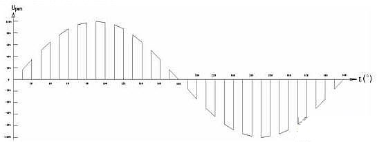
PWM Sine Wave

The element is 240v 2400w.

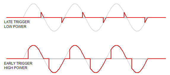
I purchased a triac based dimmer but I feel it's not the correct/most elegant solution due to noise created by chopping the wave.

Chopping the wave

I came across some high-frequency PWM solutions using IGBT or Mosfet but they seem to be switching smaller loads (100w-500w bulbs) or the components listed don't leave any headroom for my 2400w element.

The detailed description can be found here on instructables: AC-PWM-Dimmer-for-Arduino

I would like some help upgrading the components to handle such loads:

Suggested Optocoupler 4N35 (No need to upgrade)

Suggested mosfet is STP10NK60 (10a - leaves no headroom)

Suggested IGBT IRGPC40 (obsolete)

My suggested upgrade would be IRG4PC50UD (VCES = 600V @VGE = 15V, IC = 27A) with a large heatsink.

Am I missing anything here, could anyone suggest a better component?

Could anyone also shed any light on filtering any high-frequency noise on the line if there is any?

I couldn't find any off the shelf pre-made circuit board, which I found strange - everything used the old triac method or slow PWM.

\$\endgroup\$
13
  • 2
    \$\begingroup\$ Can you be clearer about your objective? I am guessing that you have grid-tie solar and are trying to make export power through the meter zero? In this case the behaviour of your meter is a critical factor. How much solar do you make (peak)? How much will you ever need to put into the hot water, after other standing loads are taken out? \$\endgroup\$
    – Henry Crun
    Commented Apr 13, 2018 at 0:13
  • 5
    \$\begingroup\$ A project that sounds troublesome. 3000W handled with a hobby circuit has a substantial death toll potential. Before you continue, think what happens, if the system has full power ON continuously and totally unattended. Could you sleep when it steams in your home after a software crash or component failure? \$\endgroup\$
    – user136077
    Commented Apr 13, 2018 at 0:25
  • \$\begingroup\$ @HenryCrun Correct! Meter is measured every cycle from what I understand. 5KW PV system peak. From my calculations, I'd like to reduce the 2400w element to 1000w (as that's what generated surplus cloudy days) by hopefully using a digital approach. In theory, tricking the smart meter (I'd need to see if it actually does in a mock-up first). \$\endgroup\$
    – Kiwi
    Commented Apr 13, 2018 at 1:47
  • \$\begingroup\$ @user287001 Thank you for the safety warning, the tank is outside, has a relief valve, multiple independent microcontrolled temperature sensors and a contactor serving the circuit on a timer and PV sensor. \$\endgroup\$
    – Kiwi
    Commented Apr 13, 2018 at 1:49
  • \$\begingroup\$ @user287001 The key thing is that the power continues to go through the mechanical thermostat regardless. (which is set higher than the electronic control point \$\endgroup\$
    – Henry Crun
    Commented Apr 13, 2018 at 3:47

5 Answers 5

5
\$\begingroup\$

I would like to add to @replete's excellent answer. The proposed high frequency switching would create a ton more noise than the simpler dimmer type phase control. Switching on and off high voltage is what creates the noise.

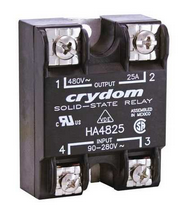
It has been my practice to always use zero crossing switches for thermal load control. In fact the easiest way to do this is to use a solid state relay (SSR) that has the zero crossing built in. Just pick out one that can handle your AC voltage and has a high enough current rating to be about 40 to 50% above your actual load requirements. Make sure to mount the SSR on a suitable heatsink and supply a fan for circulating air through the heatsink if that is required.

enter image description here

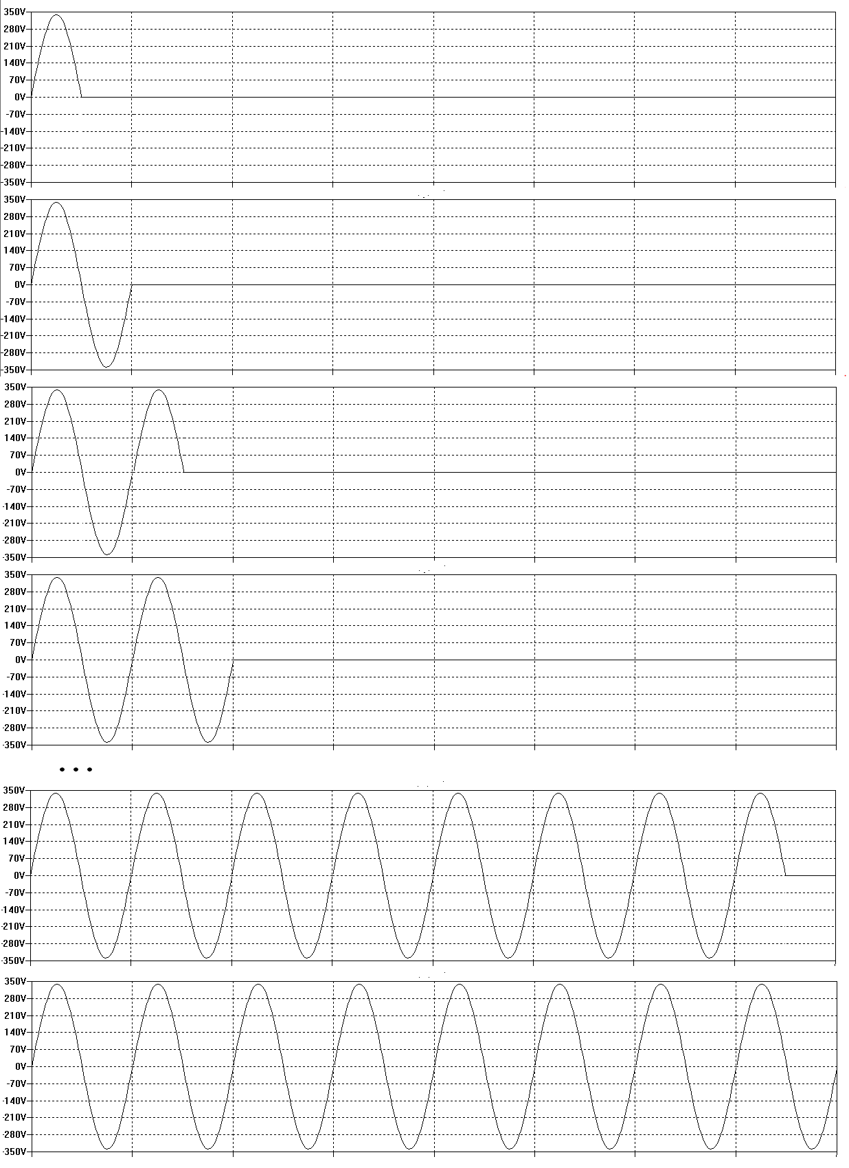
The inertia of thermal systems make it quite reasonable to operate the heater control going into the SSR as ON or OFF simply if your measured temperature is above or below the target value. However if you want to implement a simple control system you can choose to switch full ON or OFF when the temperature is beyond the desired set point by certain threshold number of degrees. Within the threshold range you could apply a certain number of AC half cycles to the heater depending how close to the reading is from the set value. A system based upon eight AC cycle times would give you 16 levels of control as depicted below:

enter image description here

\$\endgroup\$
3
  • \$\begingroup\$ Thanks. I must be so in my head about the project I forgot to mention the aim is to trick the smart meter into thinking I'm running a smaller load. I'm not concerned about PID controlling the temperature, only reducing the wattage of the element in respect to the grid tied meter. From what I understand I could run the zero cross SSR and only use a half cycle, but I'm limited by the maximum switching frequency of the SSR, therefore I'd be getting 1 half cycle every few seconds which wouldn't create enough energy to really make a difference in the element. \$\endgroup\$
    – Kiwi
    Commented Apr 13, 2018 at 1:55
  • \$\begingroup\$ I wonder if using a Mosfet with a zero cross detection and only firing every 2nd cross for 50% cycle would work. sine wave chop \$\endgroup\$
    – Kiwi
    Commented Apr 13, 2018 at 2:06
  • \$\begingroup\$ >The proposed high frequency switching would create a ton more noise than the simpler dimmer type phase control. I read somewhere they were easier to filter somehow. Unclear on that point. \$\endgroup\$
    – Kiwi
    Commented Apr 13, 2018 at 2:11
2
\$\begingroup\$

The point here is totally: How does the meter measure? If it truly measures over full cycles, then a phase control approach will work.

I also have a small grid tie system, and from looking at the power record when we are away, it appears that the meter errs considerably in favour of the power company with an error to count a small amount of incoming power, when at is actually exporting. (It is an electronic meter which record import/export separately - but we consumers don't get to see that data).

Electronic meters handle spiky current loads very poorly (especially if you have a rogowski coil sensor), and want to place any bets on which way the error will fall?

I have no knowledge of how it will work, there are multiple brands of meter used in NZ anyway. Very interested to know if you do any experiments.


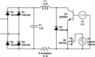
You don't need to use an AC drive. You can rectify to DC, and run the element off that. This also means that you only need a single switching transistor/fet. You can also consider a buck convertor arrangement. Buck convertors have chopped current at the input, and smooth DC at the output. However you could turn this around and connect the switch to the load, and have it choppy, and the mains end smooth. Note this is not really a 2400W regulator, it is only bearing 75V/7A or 115V/5A or 150V/4A. L1 will still be fairly fat.

schematic

simulate this circuit – Schematic created using CircuitLab


A couple of alternatives:

  • There are dual elements available, This would allow 2400,1200,600W. 3 Phase elements would allow powers 400,600,1200,1800,2400,3600. Using one of these would let you switch between power levels with zero crossing SSRs, and no noise. [Actually nz 3 phase elements]. Using 3 transistors/triacs with a common terminal, you could get 0,600,1200,1800,2400. Each switch only has to carry 5A - about 12W dissipation using triacs. 3 SPDT relays give all 6 power levels.

schematic

simulate this circuit

  • if you applied phase control to such a system with a 3ph element, you would only have much smaller power steps <600W in the phase control.

  • Change to a smaller element. If you have solar hot water like I do, a 1kW element might be fine.

  • You could use a water cooled linear regulator in series with the element. It would simply regulate the current through the element. The heat would add to the total heating. As long as you applied temperature control (at say 70C) directly to the transistors, there would be no issue with circulation pump failing. The max power is 600W in the transistors for 2400W max, and they tend to have a 100-200W limit each i.e. you need 6+ transistors like this. If your tank has a bunch of 1/2" ports in the side you could put a heat pipe into the cylinder, and not have a circulation pump.

  • You could do a hybrid with slow switching that doesn't upset the meter, and doesn't generate noise to be filtered, but dissipates say 100W in the transistors instead of 600W (no you only need one transistor) but will still need cooling.

  • You could use a choke in series. Again the choke will be 600VA or less.

\$\endgroup\$
4
  • \$\begingroup\$ Thanks @Henry Crun, the reason I was looking at doing it "intelligently" was because I couldn't get hold of a 1kw element, I had already downgraded from 5kw to a 2.4kw last year. I wanted to maximize the cloudy winter days which on average put out 1.6kw throughout the day. \$\endgroup\$
    – Kiwi
    Commented Apr 13, 2018 at 8:35
  • \$\begingroup\$ Checkout our friends in china: Several of these appear to be 3 phase, so you could get a bunch of powers aliexpress.com/store/group/AC-Water-heater-element/… I have a CN solar cylinder. I don't actually use the electric at all at present, but would like to put a variable low power in for much the same reason - I'll be measuring to see if any of these fit my cylinder. \$\endgroup\$
    – Henry Crun
    Commented Apr 13, 2018 at 9:27
  • \$\begingroup\$ BTW you might be able to experiment by just putting a big diode in series with the element. That will remove a half cycle. If you are putting out 1.2kw solar, and the meter records 0, then phase control (or integral half cycles) will obviously work. If it doesn't work the meter shows you drawing 600W \$\endgroup\$
    – Henry Crun
    Commented Apr 13, 2018 at 10:04
  • \$\begingroup\$ that is a brilliant idea, at least I can test to see if the meter picks up the missing cycle. \$\endgroup\$
    – Kiwi
    Commented Apr 13, 2018 at 10:06
1
\$\begingroup\$

XY Problem detected.

I'll ignore safety and legal aspects and comment only on the proposed control system.

Switching such a large heating element at such high frequency is pointless. You need to consider the thermal inertia of the system. It will take significant time, even on the order of 100s of ms, to respond much to a change in power input.

A first guess at the response of your system could be determined by experiments with mock-ups.

At the switching frequency and power handling required, a relay or contactor could make more sense.

Incidentally, TRIAC-based solutions for switching heating elements typically don't phase chop, they just switch on multiples of the line frequency at zero crossing. This doesn't propagate high frequency trash the way phase chopping does. Again this is because a higher speed control system is unnecessary.

\$\endgroup\$
1
  • 1
    \$\begingroup\$ @HenryCrun, my answer makes the same point as Michael's and was posted before the OP clarified his intent. Furthermore correcting misconceptions in the OP does not seem inappropriate, as Michael also did. \$\endgroup\$
    – user133493
    Commented Apr 13, 2018 at 5:41
1
\$\begingroup\$

The problem is OP doesn't have net metering, so the utility is paying a great deal less for solar than they charge for purchased power.

Triac "dimmers" won't work.

Let me erect a "straw man" so you can see why. Suppose the element is 3000W yet the solar is outputting 1200W, or 40% of the element. Why not simply switch on the water heater 4 minutes out of every 10 minutes? 40% duty cycle same as the solar, right?

Well, that won't work because solar doesn't store, and the meters do tally opposite flow separately. During the 6 minutes "off", you'll be selling 1200W back to the utility. During the 4 minutes "on" you'll be consuming the 1200W, but also taking another 1800W from the utility during those minutes. See? It doesn't work. That's exactly what you're trying to avoid (because you do not have net-metering).

10 minutes is too long an interval...
how about 1 minute? Nope, same problem, obviously.

1 second? No again, same problem.
100 milliseconds? Same problem again.
8 milliseconds? No! The same problem remains.

You'll simply be selling 1200W back to the utility during the first 60% of the sine wave, and then buying 1800W during the last 40% of the sine wave. (assuming 3000W element to make the numbers round-ish).

The 19th century solution would be a motor-operated variac, which adjusts voltage to the water heater.

The 21st century solution would be to chop the sinewave at a very short interval, such as sub-1ms. You still need to move electricity through time, but now the time interval is so short, and the amount of energy so small, that it's within reach of capacitors.

\$\endgroup\$
1
\$\begingroup\$

They make variable voltage transformers such as a variac where you can dial what you want on the output. For your system it may have to come from an industrial supplier depending on configuration. https://www.walmart.com/c/kp/variable-voltage-transformer You can also use 220 to 120 output and hook up in a buck configuration. The secondary voltage will determine how much the voltage will drop. Try starting with something in the 24V range and see how that works. Note the secondary current will need to handle the heater load. I have done this with a air duct fan motor, it works nicely. You need to be careful with your local code requirements. Mine passed inspection without problems.

\$\endgroup\$

Your Answer

By clicking “Post Your Answer”, you agree to our terms of service and acknowledge you have read our privacy policy.

Not the answer you're looking for? Browse other questions tagged or ask your own question.