3
\$\begingroup\$

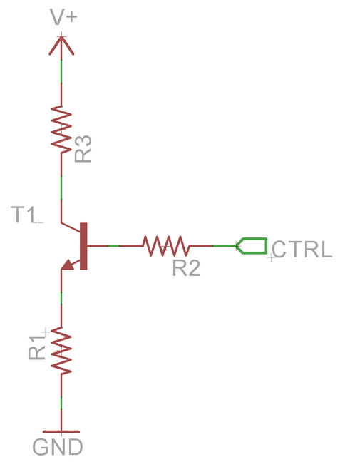
I am looking to design a simple constant current circuit to draw a precise load from a variable voltage rail. The voltage rail (V+) should be 10V-20V in normal conditions, but it is possible for V+ to be floating. The control signal (CTRL) is to be driven from an MCU on 5V rail. I am looking for 150mA from V+. Note that I am sizing resistors such that R1 and R3 will drop majority of power when V+ is 10V. The transistor would then handle the additional power as V+ goes to 20V. (So T1 will be rated for >1.65W to handle up to 11V at 150mA).

I understand that normally, R2=0ohms so I'd have a constant 4.3V at the emitter (assuming Vbe of 0.7V). That provides the easy formula of R1 = 4.3V / 0.15A.

My concern with R2=0 is that if V+ is ground or floating, there's nothing to limit the base current except for the MCU's output driver. When I add R2 to solve this concern, I'm not sure how to set the current in the circuit as it will be dependent upon base current, which I assume is going to be based on transitor's Beta.

Is there a way to create a constant current while protecting the base in my situation?

enter image description here

\$\endgroup\$
3
  • \$\begingroup\$ What tolerance do you need on the 150mA current? A circuit like this will not offer precise control. What should happen when V+ is floating or grounded? \$\endgroup\$ Commented Jul 6, 2018 at 1:53
  • \$\begingroup\$ Elliot, I shouldn't have put 'precise' in my description. I'm really only looking for +/- 10% or so. I understand variation on Vbe (esp with temperature) and MCU's output level variations are going to cause a large amount of error. When V+ is floating nothing needs to happen...I just want to keep base current in control. \$\endgroup\$
    – TFD_Jon
    Commented Jul 7, 2018 at 2:26
  • \$\begingroup\$ You have enough answers, I think, and I doubt more will be added. If any of them qualify as "an answer" to you, you should probably select it. You will get pts for that, as well. But it's a good idea to close the question if you feel it is closed. \$\endgroup\$
    – jonk
    Commented Jul 17, 2018 at 18:56

5 Answers 5

1
\$\begingroup\$

Is there a way to create a constant current while protecting the base in my situation?

Yes. First of all R3 need not exist, as it serves no useful purpose other than to get hot at high currents and waste power. R2 only needs to be 1 K to 3 K, depending on how much bias current you want to drive the transistor with. Think in terms of 1 to 10 mA of base current.

Constant current with a bjt simply means that the base to ground voltage is rigidly fixed by a TL431 or 2 1N4148 diodes in series to ground. Two diodes would lock the base to ground voltage at ~1.25 VDC.

Now subtract the Vbe drop of 0.65 volts. This means the emitter voltage is fixed at 0.65 volts. Now your constant current becomes 0.65/R. If R1 is 1.00 K then current is fixed at 650 uA. If R1 is 650 ohm then current is 1.00 mA. If R1 is 6.5 ohm the current is 100 mA. Yep, that simple.

If R1 is rated 1 watt or so then it is mostly the wattage rating of T1 to be concerned about. It will dissipate the Vce drop * current as heat.

NOTES:

1) If the drive voltage through R2 is fixed and stable then a voltage clamp is not needed, so you would adjust R1 to match the emitter voltage.

2) The constant current will be enforced unless V+ exceeds the voltage rating of the transistor or if V+ has no voltage greater than the Vce + Vbe of the transistor.

3) I prefer the diode clamps because it keeps the emitter voltage low so R1 can be low ohms to get 100 mA or more of current with little energy wasted as heat. Also R2 can have a 3.3 volt or 5 volt source and still maintain the same current. If you can keep V+ at 10 volts that will help keep T1 from getting hot.

4) R1 CANNOT be zero ohms or infinite current would flow and damage T1. Keep R1 no lower than 3.3 to 4.7 ohms.

\$\endgroup\$
3
  • \$\begingroup\$ Sparky, I appreciate your insights. I agree with your overall suggestion of adding a bit of cost to ensure Vb is regulated after a base resistor. Thanks! Some notes for you: I agree all R3 is doing is burning off energy, but remember that's all this circuit is; whether burned in resistors or transistor the energy is dumped as heat. The reason for R3 is to spread out the power burn so I can get by with a 2W transistor. On your note 4, for most applications R2 missing is the standard implementation (as long as emitter current is supplied by collector and not base!) \$\endgroup\$
    – TFD_Jon
    Commented Jul 7, 2018 at 2:46
  • \$\begingroup\$ Check out Olin's great answer explaining no base resistor here: electronics.stackexchange.com/questions/134058/… \$\endgroup\$
    – TFD_Jon
    Commented Jul 7, 2018 at 2:47
  • \$\begingroup\$ @TFDyellow. If all you needed was a controlled current dump then yes, I missed the essence of your question as a whole. You used the term "constant-current" and that threw me off topic. \$\endgroup\$
    – user105652
    Commented Jul 7, 2018 at 3:41
2
\$\begingroup\$

Some details I gather from your question, which may show my inability to read and interpret. But I'll risk it.

  • Your \$+\text{V}\$ supply can be somewhere between \$10\:\text{V}\$ and \$20\:\text{V}\$ and it can be grounded and it can be floating. And I'll just assume it can be other values, as well, but at least always somewhere between \$0\:\text{V}\$ and \$20\:\text{V}\$.
  • I have no clues about your load. Except that you would like to ensure \$150\:\text{mA}\$ for it when the I/O directs that and assuming that the voltage source can comply, too.
  • I can, however, make the argument that your load requires less than \$5\:\text{V}\$ for its own operation. This is because the \$+\text{V}\$ supply can be as little as \$10\:\text{V}\$ and you discussing this in the context of a \$5\:\text{V}\$ I/O (when you talk about the \$4.2\:\text{V}\$ emitter value.) If the BJT isn't saturated (reasonable assumption), then the collector must be above the base voltage. So this is why I can conclude this about your load.
  • You are concerned about limiting the base current into the BJT. You don't say precisely why, but I'll just run with that, too. (I do see the point where if you do NOT use a base resistor and \$+\text{V}\$ is floating then the base current could be quite high, limited only by the emitter resistor and the output compliance of your I/O pin. And if \$+\text{V}\$ is grounded then you'd have another forward-biased junction and no current limit resistor for that junction.

I'd probably recommend this very common approach, then:

schematic

simulate this circuit – Schematic created using CircuitLab

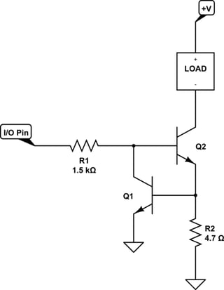
\$Q_1\$ should be kept thermally isolated from \$Q_2\$, since \$Q_2\$ is likely to get hot. Assuming the load requires \$\le 5\:\text{V}\$ and \$+\text{V}\$ can be as much as \$20\:\text{V}\$, it's pretty clear that \$Q_2\$ drops as little as \$20\:\text{V}-5\:\text{V}-1.5\:\text{V}=13.5\:\text{V}\$ and perhaps as much as \$18.5\:\text{V}\$. So you pretty much have to select \$Q_2\$ so that it is well-able to dissipate around \$3\:\text{W}\$. However, \$Q_1\$ is doing the current-monitoring function using its \$V_\text{BE}\$, which is already sensitive to temperature. So thermal separation may make things more predictable. (However, ambient temperature will still have an effect. If you want to make this work repeatably over a wide ambient temperature range, a different circuit is needed.)

The above circuit will require \$\lt 3\:\text{mA}\$ from your I/O pin, regardless of what \$+\text{V}\$ is doing. Even if \$+\text{V}\$ is grounded, since as you can see there is \$R_1\$ to intercede in all cases.

\$\endgroup\$
2
  • \$\begingroup\$ Thanks Jonk. I agree with your answer, and see this as another approach as Sparky mentioned (creating constant voltage at Vb; using transistor rather than diodes). \$\endgroup\$
    – TFD_Jon
    Commented Jul 7, 2018 at 2:52
  • \$\begingroup\$ @TFDyellow Do you feel you understand the concept here? The basic idea is that R1 provides more than enough base current for Q2. However, Q1 monitors the drop across R2 and "sinks" excess current from R1 before it can get to the base of Q2, when and where needed. So Q1 is monitoring the voltage across R2, adjusting how much current it sinks away from Q2's base. All the I/O pin does is supply an excess amount and allows Q1 to figure out how much to sink away in order to hold one VBE drop across R2. \$\endgroup\$
    – jonk
    Commented Jul 7, 2018 at 3:08
1
\$\begingroup\$

There are a number of problems here:
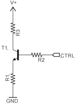
  1. Draw the schematic with logical flow left to right. Fortunately what you have is simple enough to understand anyway, but it's still annoying to look at.
  2. You are clearly using Eagle, so there is no excuse for dumping screen shots on us. The different colors for nets and symbols and the little origin crosshairs for each component of the drawing have no relevance to us. They are something between you and your software, but inflicting them on others is rude and detracts from the message. Eagle has easy ways to export schematics to image files. Use them.
  3. Fix the orientation of text. There is no excuse for the R1 and R3 component designators to be rotated. There was plenty of room, and nothing stopping you from presenting the schematic properly. Don't be so lazy. Remember that you are asking volunteers for a favor.

I was going to get into circuit details, but I ran out of time. I gotta go now. Maybe I'll remember to come back later and talk about the circuit.

Added about the circuit

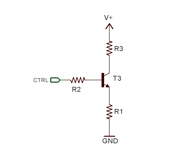
I see you have fixed the schematic, so now we can talk about the circuit.

You are essentially trying to use a common base configuration as a current sink. That's fine, except when the transistor doesn't get enough collector voltage, and too much of the emitter resistor current must come from the base. The circuit driving the base can't handle that.

One solution is more gain. During normal operation, that means there is less current drawn from the digital output, so any resistance in series with it causes less of a voltage drop. Here is one idea:
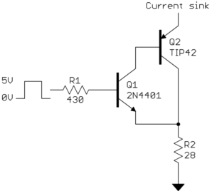
This still uses the same principle of a fixed base voltage on Q1 causing a fixed voltage across R2, which causes a fixed current to be sunk. The difference is the addition of Q2, which provides more current gain.

In this example, Q1 can be counted on to have a gain of 40, and Q2 of 30. The overall gain from the base current of Q1 to the collector current of Q2 is therefore at least 1200. The maximum Q1 base current during normal operation is therefore (150 mA)/1200 = 125 µA.

R2 is what it needs to be to cause about 150 mA at 4.3 V. R1 is then sized to limit the current when Q2 is unpowered. Since you didn't provide any specs, I arbitrarily picked 10 mA for the maximum safe current that the digital output can source.

Now we can work backwards and see what the error is due to R1. We know the maximum current thru R1 will be 125 µA, so the maximum voltage across it will be 54 mV. That amounts to a 2 mA error when reflected across R2, or about 1.3% of your 150 mA target. There are other larger sources of error here anyway, particularly the actual B-E voltage of Q1.

\$\endgroup\$
6
  • \$\begingroup\$ I do apologize Olin. This is my first post on Stack Exchange and you are 100% correct that I copied in the schematic without the effort I would've given my clients. I will be sure to put more effort in my future posts. I know that you have provided great advice on similar circuits so I very much hope you can look past these presentation flaws here. \$\endgroup\$
    – TFD_Jon
    Commented Jul 7, 2018 at 3:03
  • \$\begingroup\$ Please remember to come back later and please talk about the circuit Olin! :) \$\endgroup\$ Commented Jul 9, 2018 at 7:56
  • 1
    \$\begingroup\$ @abd: Added. -- \$\endgroup\$ Commented Jul 9, 2018 at 11:04
  • \$\begingroup\$ Thank you Olin. I understand your approach here; increase the gain to allow base current to be small so a base resistor can be added without large error. I am a bit curious if we're adding a transistor why you suggest this approach instead of Jonk's suggestion of using the transistor to provide negative feedback on base current. In that case, the only error in the circuit would come from Vbe of the regulating transistor (Q1 in his schematic, which isn't getting hot) and the emitter resistor tolerance. For my application requirements it doesn't matter, but I'm curious in your insights. \$\endgroup\$
    – TFD_Jon
    Commented Jul 9, 2018 at 15:50
  • \$\begingroup\$ @TFD: Different tradeoffs. In his, the voltage reference is only B-E of Q1. In mine, it's the 5 V digital level minus a B-E drop. The latter is less susceptible to temperature and parts variations, but dependent on the 5 V supply. Note that my Q1 doesn't get hot either. His Q2 should be a power transistor, but the choice will be limited since it must have a gain of 63. His has a wider compliance voltage range. From the specs you've stated, both circuits should work for you. \$\endgroup\$ Commented Jul 9, 2018 at 17:50
0
\$\begingroup\$

Call me crazy, but I don't think R2 matters at all if V+ is ground of floating (or ever?). Just leave it out. The operating principle of a BJT is that base-emitter current is amplified (by the transistor's current gain factor beta) to generate the collector-emitter current, and the base-emitter junction incurs a diode voltage drop...

If V+ is floating, no collector-emitter current can develop, because what would be the source of that moving charge (conservation of energy and all that).

If V+ is ground, again no collector-emitter current can develop, because current flows from a higher potential to a lower potential. If both ends of that path are at GND, no current can flow between them.

Unless I'm missing something, in which case I'm sure the community will chime in.

\$\endgroup\$
6
  • \$\begingroup\$ Of course, R2 matters! The input resistance rin of the BJT at the base node is not infinite . That means: The control voltage CTRL drives a current through a voltage divider R2-rin. And it is the VOLTAGE across the B-E path which determines the collector ciurrent (and NOT the base current). \$\endgroup\$
    – LvW
    Commented Jul 6, 2018 at 8:51
  • \$\begingroup\$ @LvW ok, lets make this a side-band teachable moment then. My recollection was that Ic = beta * Ib, and that V_be was basically 0.7V fixed (to a first order), but I suppose those relation depends on a circuit topology that I'm forgetting or that is not applicable here? Regarding R2, what I meant was that it doesn't really accomplish anything that simply changing the value of R1 alone wouldn't also accomplish? \$\endgroup\$
    – vicatcu
    Commented Jul 6, 2018 at 14:16
  • \$\begingroup\$ No doubt about it. The control voltage Vbe depends on R1 as well as R2. But your statement was "I don't think R2 matters at all". \$\endgroup\$
    – LvW
    Commented Jul 7, 2018 at 9:37
  • \$\begingroup\$ More than that, as far as I understand the question, it is the control signal via R2 only that is to be used for changing the DC conditions. \$\endgroup\$
    – LvW
    Commented Jul 7, 2018 at 9:41
  • \$\begingroup\$ To be clear, though, it depends if the transistor is being operated in Saturation or Active regions which set of equations are in play. What I described assumes the transistor is in saturation, which may have been a bad assumption. \$\endgroup\$
    – vicatcu
    Commented Jul 7, 2018 at 17:36
0
\$\begingroup\$

Please try this.

enter image description here

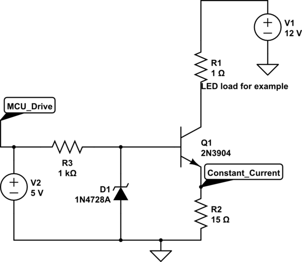
  1. Let R2 be 1 kilo ohms
  2. Place a zener of reverse voltage of say 2.7 V (for discussion sake) between base and the ground and make sure it is biased properly when MCU is driving it.
  3. Change emitter resistor(R1) to 14 ohms
  4. Now we have a constant 2.7 V applied across the base whenever the zener is driven (reverse voltage)
  5. Assuming base drop of 0.7 V, we will have 2 V across this emitter resistor all the time.
  6. It corresponds to a current of 2 V / 14 ohms which is roughly 142 mA.
  7. Note that this is independent of positive voltage (10 V to 20 V)
  8. Please find a darlington transistor for high ß
  9. Depending of MCU voltage you can choose zener voltage and do similar math again to choose new emitter resistor value
  10. No. Doesn't work with V+ floating.
  11. R3 can be your load (LEDs for example)

All above points refers to reference designators in OP's question


Will upload the circuit soon

Example only Schematics:

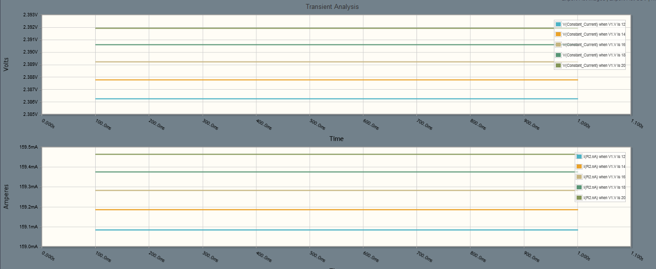
Below is the sweep done for 12 V supply in 2 V steps until 20 V. you can run the simulation and tweak values. enter image description here schematic

Below text uses references in my circuit

Zener and R2(in my circuit) together act as negative feedback for this system and hence when current tries to increase, the emitter voltage will increase which tends to decrease the applied base emitter voltage for the transistor there by reducing the gain a little and the nice the collector current accordingly.

\$\endgroup\$
1
  • 2
    \$\begingroup\$ I think, the emitter resistor R2 is the part which causes negative feedback (not R1). \$\endgroup\$
    – LvW
    Commented Jul 6, 2018 at 9:56

Your Answer

By clicking “Post Your Answer”, you agree to our terms of service and acknowledge you have read our privacy policy.

Not the answer you're looking for? Browse other questions tagged or ask your own question.