3
\$\begingroup\$

I am studying this circuit in my course:

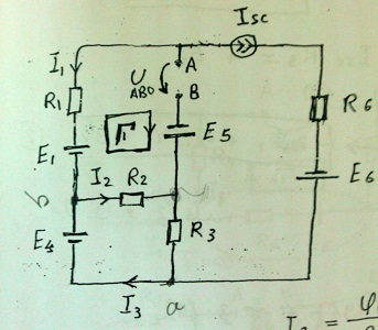
enter image description here

AB is opened, E1 = E5 = 10V, E4 = 40V, R1 = 2 Ohm, R2 = 4 Ohm, R3 = 6 Ohm, R6 = 6 Ohm

I want to write KVL for the Loop 1, what I do usually is defining the voltage drops polarity across each element (resistors in this circuit) but here I have many voltage sources.

Now the question that confused me is: How do I define the voltage drops polarity? According to an origin voltage source (The highest one, or the one the problem is referring to)? Or I just define the polarity of each element according to its branch and its source separately?

Thank you very much in advance.

\$\endgroup\$
5
  • \$\begingroup\$ possible duplicate of Solving this circuit using node analysis \$\endgroup\$ Commented Sep 4, 2012 at 18:47
  • 1
    \$\begingroup\$ @BrianCarlton, I don't think this is a duplicate. KCL is used in node analysis, not KVL. \$\endgroup\$ Commented Sep 4, 2012 at 19:28
  • \$\begingroup\$ Have you been taught about the superposition principle yet? This is the basis of how you deal with a circuit that has multiple independent sources. \$\endgroup\$
    – Dave Tweed
    Commented Sep 4, 2012 at 21:05
  • \$\begingroup\$ @DaveTweed, Yes I have studied this principle with waves and Alternative Current power sources... How do I match this principle with this condition? \$\endgroup\$ Commented Sep 5, 2012 at 8:41
  • \$\begingroup\$ It works just as well with DC sources, too. You consider the effects of each source one at a time, replacing each other voltage source with a short circuit, and each other current source (there are none in this particular circuit) with an open circuit. I think if you do this, you'll see that the problem is greatly simplified and you'll gain some important insights. \$\endgroup\$
    – Dave Tweed
    Commented Sep 5, 2012 at 11:33

1 Answer 1

3
\$\begingroup\$

By the passive reference convention, the current enters the positive terminal of a passive element such as a resistor. The voltage source polarity is given by the symbol.

So, KVL clockwise around loop 1 is:

\$U_{AB} - E_5 - I_2 \cdot R_2 - E_1 - I_1 \cdot R_1 = 0\$

Or,

\$U_{AB} = E_5 + I_2 \cdot R_2 + E_1 + I_1 \cdot R_1\$

Consider how you would measure the voltage across R2. How do you choose which polarity to measure? You have a choice of where to place the red and black leads so which one is correct? Obviously, both are. If the red lead is on placed on the more positive lead of the resistor, the measured voltage will be positive. If the red lead is placed on the more negative lead, the measured voltage will be negative. Choosing the reference polarity of the voltage variable (the variable you solve for in your equations) for R2 works in exactly the same way.

You are free to choose the reference polarity and, after you solve the equations, if you find that the voltage across R2 is negative, you know that the end you chose to be positive is actually the more negative end. The point is, just as with the voltmeter leads, the reference polarity is arbitrary. However, it is always a good practice to use the passive reference convention so, as in your example, if you want the voltage across R2 in terms of I2, you should should choose your reference polarity such that I2 enters the positive terminal.
\$\endgroup\$
7
  • \$\begingroup\$ A is positive and B is negative so the current flows from A to B. Do I understand that the polarity of each element is defined according to the current flowing through it? What if the problem doesn't shows the current flows in the branches of the circuit? \$\endgroup\$ Commented Sep 5, 2012 at 9:32
  • \$\begingroup\$ There is no current from A to B as there is an open circuit there. Thus, there is no current through E5. The passive reference convention is that the current enters the positive terminal of passive elements. So, if you choose the voltage polarity first, then draw your current reference direction entering the positive terminal. For voltage sources, the polarity is given. \$\endgroup\$ Commented Sep 5, 2012 at 11:05
  • \$\begingroup\$ Here lies the confusion... how do I choose the polarity of the elements if there is one terminal connected to two power sources? Look at R2, what would its left terminal be? positive or negative? My thought is it should take its polarity from E4 neither than E1, because E4(40V) is greater than E1(10V). What do you think? \$\endgroup\$ Commented Sep 5, 2012 at 18:10
  • 1
    \$\begingroup\$ (continued). You are free to choose the reference polarity and, after you solve the equations, if you find that the voltage across R2 is negative, you know that the end you chose to be positive is actually the more negative end. The point is, just as with the voltmeter leads, the reference polarity is arbitrary. However, it is always a good practice to use the passive reference convention so, as in your example, if you want the voltage across R2 in terms of I2, you should should choose your reference polarity such that I2 enters the positive terminal. \$\endgroup\$ Commented Sep 5, 2012 at 19:39
  • 1
    \$\begingroup\$ Thank you very much, that was my question.. you may edit your answer so I mark the question as "Answered" :) \$\endgroup\$ Commented Sep 5, 2012 at 20:10

Your Answer

By clicking “Post Your Answer”, you agree to our terms of service and acknowledge you have read our privacy policy.

Not the answer you're looking for? Browse other questions tagged or ask your own question.