Introduction
First off, I'd like to let you know I am a beginner at electronics so some of the stuff I say might be very wrong.
What I want to make is a 'spark generator' for lighting some gases in a chemistry project.
I have been having a bit of fun just shorting a mini capacitor bank and seeing the spark it produces. Now I want to include a remote switch so I can discharge them from a distance.
I have decided to use a transistor controlled by an Arduino Uno (Arduino is controlled by nrf24l01 module).
Circuit

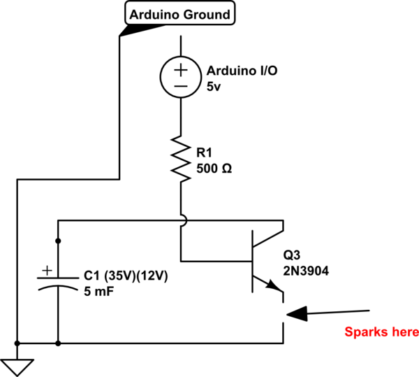
simulate this circuit – Schematic created using CircuitLab
Sorry if my circuit drawing is bad, here is a written description if you prefer:
- capacitors are 35v (I only charge them to 12v) 1000uF and there are 5 in parallel with eachother
- arduino I/O pin connects to a 500 ohm resistor, which connects to base pin of transistor
- transistor collector pin is connected to capacitor+
- transistor emitter pin is connected to capacitor-
- the arduino ground is also connected to capacitor- (HAVE NOT TESTED!) -
I have made separate cables for charging them up. Essentially I have charged capacitors hooked up to a transistor switch which is controlled by an arduino.
Here is what I need help with
Previously to making this circuit I had tested it without arduino ground connected to capacitor-. It did not work which is what led me to attach arduino ground to capacitor-. I am concerned that shorting the capacitor bank will actually just flush it all into the arduino ground and fry it. I was tempted to try it but I came here for reassurance from someone more knowledgeable. Thanks

