1
\$\begingroup\$

Regarding my previous question, I decided to use a “fully differential amplifier” to obtain a voltage gain of 10. The source and ADC are also differential. The source is unipolar and its output resistance is given as 100 Ohm. I want to amplify the +/-200mV source voltage by gain of 10 or more. ADC input can be set to +/-5V or +/-10V. Below I have drawn the schematics:

enter image description here

Above ADC and the amplifier are just representative. ADC is actually a channel of a differential ended data acquisition board. OPA 1632 represents a fully differential amplifier but it is designed for audio. My freq of interest is not audio, it is actually DC to 150Hz and need low noise as possible.

If this topology is correct, before I start to build this I noticed I have some inexperience about some critical decision.

I summarized the questions for clarity:

  1. I want to use 5 meters of STP cable between the source and ADC. Should the amplifier be right after the source or right before the ADC?

  2. As far as I understand the voltage gain is 1+R3/R1 = 1+R4/R2 where R3=R4 and R1=R2. But what values of resistors are reasonable?

  3. R1, R2, R3 and R4 will have tolerances. In that case how can matched resistor arrays be configured to obtain better CM noise immunity?

(Schematic does not show an anti-aliasing filter)

\$\endgroup\$
1
  • \$\begingroup\$ you say you have a unipolar source but diagram shows a differential source. What do you mean? Or is VG1 just 0V? \$\endgroup\$ Commented Feb 10, 2021 at 13:29

2 Answers 2

1
\$\begingroup\$

(1) It should be right at the source. There's no point turning into a differential signal after all the noise on the cable has gotten into the signal.

(2) The values of resistance that are reasonable depend on your op-amps drive capability as well as your source's drive capability/output impedance. If both your op-amp and source can drive a lot of current you can use lower value resistors. Definitely do not go below 1K for the total resistance in any feedback path. Keeping it between 5-10K is probably reasonable though you can probably go as low as 3K and as high as 20K. This is for the total resistance in a feedback path, not any individual resistor. Higher resistances are easier for the source and amp to drive but produce more noise. Lower resistances are the opposite.

(3). The amp rejects signal that are the same on both inputs so if equivalent resistors are different between the inputs then signals that are the same and should be rejected will appear to be different and be accepted, while signals that are different and should be rejected may appear the same and be accepted. Matching resistors between feedback loops helps alleviate this.

Discrete matched resistors help alleviate this. Matched resistor arrays are even better because resistances drift with temperature and nothing guarantees the two resistors are at the same temperature. Being on the same package and manufactured at the same time ensures nearly identical temperature coefficients as well as tight thermal coupling so the resistors stay as similar as possible even while drifting.

\$\endgroup\$
13
  • \$\begingroup\$ Thanks could you also show or draw/sketch how such matched resistors will be placed in the circuit? Its a bit confusing since they are not seperate. There are four resistors in my circuit. I never used matched resistors before. \$\endgroup\$
    – user1999
    Commented Feb 15, 2019 at 20:32
  • \$\begingroup\$ I won't provide an image but I shouldn't really need to since it's not difficult. Just look at both signal legs of your circuit. Each resistor in the same position should be matched and in the same array with the other. Note that pairing like this only helps CMRR. For example, pairing R1/R2, R3/R4, R5/R6 into their own arrays would help with CMRR. But then R1 and R3 can still drift which would make your gain vary over temperature. Thus ideally, you want EVERY resistor there to be in the same array but that is often just not possible. \$\endgroup\$
    – DKNguyen
    Commented Feb 15, 2019 at 20:35
  • \$\begingroup\$ I see, very informative. Are there such arrays including for example two 1k and two 10k in the same array? \$\endgroup\$
    – user1999
    Commented Feb 15, 2019 at 20:40
  • \$\begingroup\$ Yeah, they come in all sorts of combinations of values pairs. They also exist in more than just pairs. They can also be very expensive. Search mouser or Digikey. I think you would have to be very lucky and pay a pretty penny to find a single array that has everything you need though. \$\endgroup\$
    – DKNguyen
    Commented Feb 15, 2019 at 20:41
  • 1
    \$\begingroup\$ 1. Your gain is not going to be 10. It's going to be 11 (I assume R5 and R6 are not resistors but is the signal output impedance). 2. electronics.stackexchange.com/questions/263424/… 3. ADC Common mode and noise filtering (also anti-alias): Look at Figure 46-49 of the ADC datasheet for the common-mode filters on the ADC input. 4. Use C0G capacitors in the signal path. Others types have DC-bias and microphonic effects. \$\endgroup\$
    – DKNguyen
    Commented Feb 15, 2019 at 20:52
0
\$\begingroup\$

[Summary: using the concepts of ThermalShorts and ThermalOpens, with 0.1 watt from the opamp in a central location, with perfectly-symmetric layout inside a ThermalOpen gap in the copper, the temperature mistracking should be about 2/8 degree Centigrade (7/8 degree, if only ONE Ground plane used)]

Let's talk about thermal management, such as creating thermal_shorts and thermal_opens, to steer heat flows along paths that will cause the smallest possible temperature gradients.

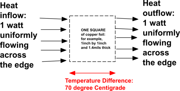
First point to learn is the thermal_resistance of standard thickness (1.4 mils, 35 microns) 1 ounce/squareFoot copper foil: 70 degree Centigrade per watt, for heat flowing from edge to edge of a square of foil. What does this mean?

schematic

simulate this circuit – Schematic created using CircuitLab

What does this mean? If your amplifier has 0.1 watt of heat, and that heat exits the IC on one side, thru 1 cm wide piece of foil, then every 1cm*1cm will cause 7 degree C additional temperature rise. And your gain-set resistors do not need any temperature gradients, or the resistor values will be mismatched, and your CMMR will be impaired.

What to do? Lets build ThermalShort (OK, close to a short) and examine the heat flow patterns.

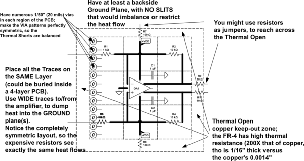
Below, the example has the primary heat source (the IC) in the middle of EIGHT squares. At 0.1 watt, the 7 degree Centrigrade is divided by 8, to 7/8 degree Centigrade maximum thermal error. If you use THREE GROUND planes, connected with VIAS every 5mm, your thermal error should be another 3:1 smaller, to about 2/8 degree Centigrade.

Lets use a 4-layer PCB, and use 2 or 3 of the layers as GROUND, with VIAS every 5mm (1/5 inch) so the 3 layers are highly connected thermally. By the way, vias with approximately the same periphery as thickness (in 1/16 thick PCB, use a 1/(3*16) or 1/48" diameter drill), will have 1:1 ratio and will also look like 70 degree Centigrade per watt of thermal resistance.

OK so what? Consider this:

schematic

simulate this circuit

Notice the totally SYMMETRIC placement of the heat-sensitive resistors; notice the central placement of the primary heat-generator (the IC). The resistors will also generate heat, with the heat exiting thru the WIDE PCB traces and then passing thru 1/32" thick (or 1/50th", for 4 layers, FR-4.

\$\endgroup\$

Your Answer

By clicking “Post Your Answer”, you agree to our terms of service and acknowledge you have read our privacy policy.

Not the answer you're looking for? Browse other questions tagged or ask your own question.