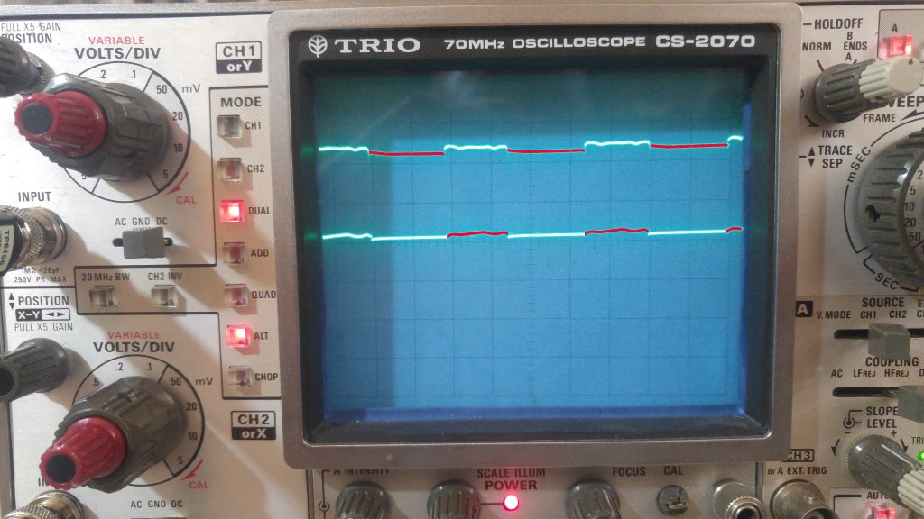
Using a HCF4049 to invert a signal, I simply fed the input to one of its not-gates and got its output. Here is the result:
The highlighted red lines is the output of the not-gate. (Yep! my analogue oscilloscope can display colors, it knows how to use my laptop ;D )
The output signal has a smaller peak-to-peak value! Both channels are set to 2 volt/div. So the output's peak-to-peak voltage is about 0.4 to 0.6 volts less than the input. Why?
I switched the probes and also the channels to check if there is any problem with the oscilloscope calibration. But got the same result.
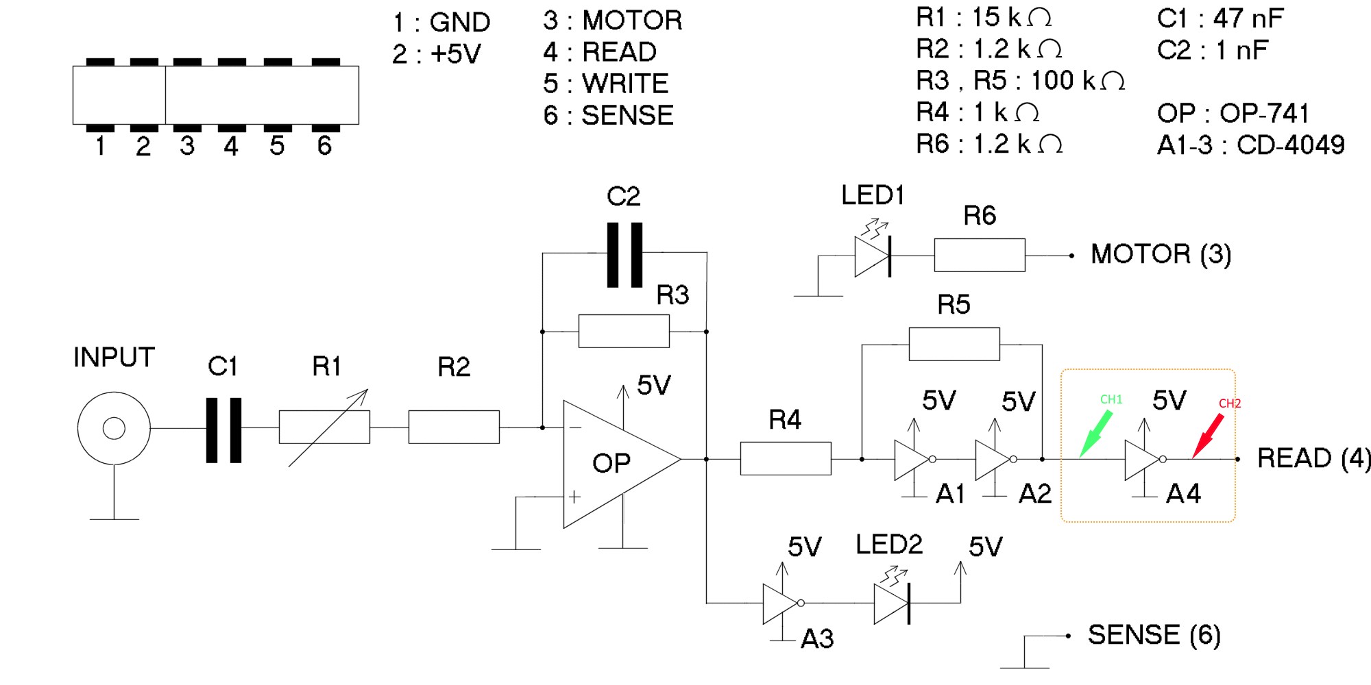
If it is important, here is the original circuit (the link to schematics is in the middle of the page.)
This is my modified version. I have added A4, and the CH1 and CH2 are where the probes are.
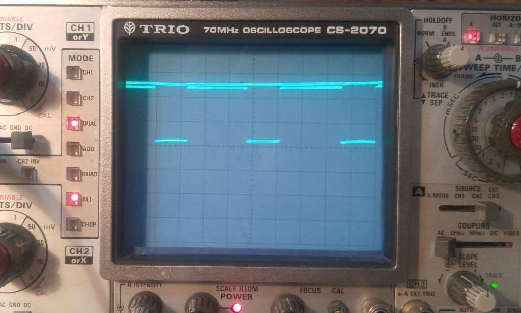
To check the oscilloscope accuracy, here the CH1 is connected to 5V and the CH2 is the output as before:


