19
\$\begingroup\$

Lithium coin cells are rated for fairly low standard current draws, on the order of 1 to 5 mA. Also, while they allow greater pulsed current draws (i.e., periodic bursts), this appears to be detrimental to cell capacity (and also can cause a drop in the voltage during the pulse).

I am bringing up this topic out of interest in applicability of coin cells for general use-cases (such as LEDs or more recently low-power wireless transmission), so I don't have a specific circuit in mind.

But imagine two scenarios, one a low-duty cycle and one a more demanding case:

  • Case A: Load draws 25 mA for 25 milliseconds once every 2.5 seconds.
  • Case B: Load draws 50 mA for 100 milliseconds once every 1 seconds.

I'm interested in an analysis of whether a capacitor-based reservoir can be applied to (and thus, whether it is wise to) run either of the pulse-draw cases above off a coin cell.

Note 1: In both cases, I'm considering a generic situation with Coin cell --> 3.3V Boost regulator --> LOAD [microcontroller + LEDs with series resistors + Wireless module + etc]. And the Cap/Supercap parallel to the load supply.

Note 2: I'm aware that one could use Li-ion/LiPo batteries but they have higher self-discharge (whether due to their chemistry or due to their protection circuitry), so they may not be ideal for, say, a wireless temperature logger that transmits once every hour.

Relevant documents: The following datasheets show various pieces of information, including pulse discharge characteristics, operating voltage vs. load, etc.:

  1. Energizer CR2032 Datasheet
  2. Panasonic CR2032 Datasheet
  3. Sony CR2032 Datasheet
  4. Maxell CR2032 Datasheet

In addition, the following documents discuss some empirical assessment / qualitative discussions about running somewhat large loads (with peak current draw on the order of tens of milliamps) using a coin cell:

  1. TI App note: Coin cells and peak current draw

  2. Nordic Semiconductor App note: High pulse drain impact on CR2032 coin cell battery capacity

  3. Freescale App note: Low Power Considerations for ZigBee Applications Operated by Coin Cell Batteries

  4. Jennic App note: Using Coin Cells in Wireless PANs

\$\endgroup\$
5
  • \$\begingroup\$ Do you have any manufacturer's data regarding pulse current limitations on lithium coin cells? I have a collection of coin cell data sheets, but they don't really discuss current under pulse loads. \$\endgroup\$
    – markrages
    Commented Oct 10, 2012 at 18:52
  • \$\begingroup\$ @markrages: Added datasheets (as well as some app notes) at end of question, which have SOME (albeit limited) information about pulse characteristics. \$\endgroup\$
    – boardbite
    Commented Oct 10, 2012 at 19:31
  • \$\begingroup\$ The 25 mA, is that a constant current like in Dave's interpretation, or a more common setup with a series resistor for the LED? The current source gives you an easy solution (see Dave's answer), but may not be what you'll see in the wild. \$\endgroup\$
    – stevenvh
    Commented Oct 10, 2012 at 20:30
  • \$\begingroup\$ @stevenvh: Question updated: "Note 1" \$\endgroup\$
    – boardbite
    Commented Oct 11, 2012 at 4:52
  • \$\begingroup\$ Searched high and low for that Jennic AN, it's gone from the interwebs. Only references around, no caches either. \$\endgroup\$
    – kert
    Commented Apr 22, 2017 at 20:25

4 Answers 4

10
\$\begingroup\$

The calculation is straightforward. The capacitor size is simply a question of how much voltage drop you can tolerate over the duration of the pulse. The average current from the battery is a function of the duty cycle.

ΔV = I × Δt / C

Solving for C gives:

C = I × Δt / ΔV

Let's assume you can allow ΔV = 0.1V. For your first example, this works out to:

C = 25 mA × 25 ms / 0.1 V = 6.25 mF

The average current draw is 25 mA * 25 ms / 2.5 s = 0.25 mA.

For the second example, the numbers work out to:

C = 50 mA × 100 ms / 0.1 V = 50 mF

Average current = 50 mA * 100 ms / 1.0 s = 5 mA.

\$\endgroup\$
2
  • \$\begingroup\$ @Dave - You don't need resistors because you're assuming constant current sources/sinks. That's how you get linear equations instead of exponential. True, I added resistors which aren't in the question, but you add current sources which aren't there either :-) \$\endgroup\$
    – stevenvh
    Commented Oct 10, 2012 at 19:53
  • 1
    \$\begingroup\$ @stevenvh: Actually, they are; the original question was posed in terms of current pulses. For this type of general feasibility question, linearizing the equations (while understanding that this is an approximation) is perfectly legitimate. \$\endgroup\$
    – Dave Tweed
    Commented Oct 10, 2012 at 20:15
7
\$\begingroup\$

The parallel capacitor will be suitable, but only if you choose it carefully.

As explained by @stevenvh, a capacitor parallel to the load is suitable for pulsed loads. The important characteristic of the capacitor (apart from its capacitance C) is its insulation resistance (IR). The insulation resistance determines the leakage of charge from the capacitor while waiting between pulses.

Ceramic capacitors have high IR, and Murata gives information in their datasheets which can obtained from http://www.murata.com/products/capacitor/design/data/property.html. Their X5R series is specified with $$ \mathrm{IR}_\mathrm{X5R}\cdot C = 50~\Omega\cdot\mathrm{F} $$ which means that 1000 μF made up of parallel capacitors has a resistance of 50 kΩ. $$ \mathrm{IR}_\mathrm{X5R} = 50~\Omega\cdot\mathrm{F}/C = \frac{50}{1000\cdot 10^{-6}} = 50~\mathrm{k}\Omega $$

At 3 V you will have a leakage current of 60 μA, which is comparable to your load's average current draw.

To improve this you can try another type of capacitor. NP0 or C0G capacitors have less leakage but they will take up much more PCB space. $$ \mathrm{IR}_\mathrm{NP0}\cdot C = 500~\Omega\cdot\mathrm{F} $$

\$\endgroup\$
6
\$\begingroup\$

At first sight case A doesn't look like it's going to cause us trouble (but wait!). Back-of-envelope-calculation: the duty cycle is only 1 %, so the 25 mA will have to be compensated by a 250 µA charging current. That's for constant current, which varies the capacitor voltage linearly with time.

\$ C = \dfrac{t_1 \times I_1}{\Delta V} = \dfrac{25 ms \times 25 mA}{\Delta V} = \dfrac{625 \mu C}{\Delta V} \$

\$ C = \dfrac{t_2 \times I_2}{\Delta V} = \dfrac{(2.5 s - 25 ms) \times 253 \mu A}{\Delta V} = \dfrac{625 \mu C}{\Delta V} \$

So \$C\$ will be determined by the voltage drop you'll allow. If you would allow 200 mV drop, to 2.8 V, then you'd need a capacitor of 3100 µF.


But in most real-world applications current won't be constant, and charging/discharging the capacitor over a resistor will go exponentially. You have only 1 V difference between the capacitor's 3 V and the LED's 2 V, and you don't want to drop the capacitor's too much before the 25 ms are over; not that fading will be noticeable as such, but the average brightness will be. So assuming a maximum allowed 200 mV drop in 25 ms will mean:

\$ (3 V - 2 V) \times e^{\left(\dfrac{-25 ms}{R C}\right)} + 2 V = 2.8 V \$

then \$ R C\$ = 0.11 s.

For recharging we'll have to set an end voltage; if we would like to recharge to the full 3 V it would take an infinite time. So if we set our target at 99 % of 3 V we can write a similar equation:

\$ (3 V- 2.8 V) \times e^{\dfrac{-(2.5 s-25 ms)}{R C}} = 3 V \times 1 \% \$

then \$ R C \$ = 1.30 s.

Yes, that's different \$ R C\$ times because the \$ R\$ is different: for the discharge it's the LED's series resistor, for the recharging it's the resistor from the battery.

For the series resistor with the LED we can calculate

\$ R_1 = \dfrac{2.9 V - 2 V}{25 mA} = 36 \Omega\$

The 2.9 V is the average voltage during discharging, which allows us to calculate the average current. The begin current will be 27.5 mA, but that's not going to be a problem. I calculated the 2.9 V simply as the average between 3 V and 2.8 V, but that's quite OK, over this short time you can assume the discharge to be nearly linear. (I just did the calculation with the integral of the discharge curve, and that gives us 2.896 V average, which confirms that; the error is only 0.13 .)

Since we know \$ R_1 C\$ and \$ R_1\$ we can find \$ C\$:

\$ C = \dfrac{0.11 s}{36 \Omega} = 3100 \mu F \$

And now we can find the charging resistor too:

\$ R_2 = \dfrac{1.30 s}{3100 \mu F} = 420\Omega \$.

Note that the capacitance is the same as with our constant current charging and discharging. That's because the short discharge can be approximated well as linear, like we saw earlier, and also I rounded the values.

\$\endgroup\$
3
  • \$\begingroup\$ Where did all these resistors come from? They're certainly not part of the original question, and if you were really concerned about running something from a coin cell, you wouldn't be wasting a significant fraction of your energy in resistors! \$\endgroup\$
    – Dave Tweed
    Commented Oct 10, 2012 at 19:45
  • \$\begingroup\$ @Dave - Are you going to short-circuit the capacitor over the LED? You'll have a lot more than 25 mA then. Granted, only for a short time, but nevertheless the LED wouldn't like it. For charging I'll have to see if I can make use of the battery's internal resistance, but IMO a series resistance will still be needed: otherwise the capacitor discharge to 2 V will also brown-out the microcontroller, if it's directly connected. Remember that we don't have a hard 3 V, but a 3 V with a series resistance, which will take the difference between the 3 V and the capacitor's 2 V. \$\endgroup\$
    – stevenvh
    Commented Oct 10, 2012 at 19:51
  • \$\begingroup\$ A resistor is just one of many ways to control current. Appropriate active circuits will be much more efficient. The original question was about the feasibility of the general concept. \$\endgroup\$
    – Dave Tweed
    Commented Oct 10, 2012 at 20:11
3
\$\begingroup\$

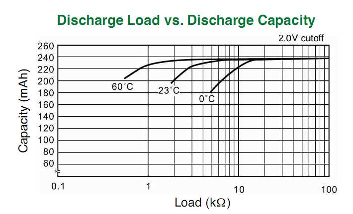
It is important to choose the right size cell and supplier for your application and understand the loss of capacity drops a lot when you exceed the rated load. They need to supply the capacity vs load resistance for your operating temperature. If not given you calculate the battery's ESR at rated cutout voltage and load.

Keep in mind the initial ESR is much smaller e.g. 10% cutout ESR and that also degrades from cold temperature by almost 3x from 23'C to 0'C. They means your capacity is reduced.

enter image description here

The load ESR increases with duty factor (d.f.) ESR = V/I * 1/d.f.
In both your Cases A & B, d.f. is 2.ms/2.5s = 0.01 ( 1%)

Let's start with these values and neglect ESR of battery.

  • Case A, 3V@25mA, 1% d.f. ESR= 12 kΩ (assuming linear for now)
  • Case B, 3V@50mA, 1% d.f. ESR= 6 kΩ ( " ")

Your Vmin or regulation spec,. will greatly affect the lifetime reduction from rated capacity. Many suppliers use 33 to 50%, you might need 10~20%.

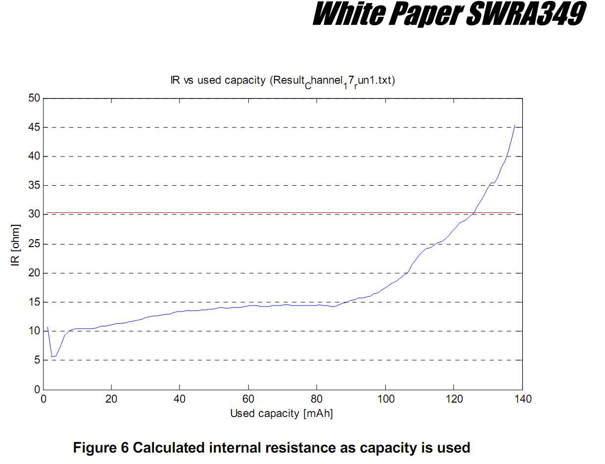
Note below the graph of ESR of the battery rises sharply with loss of capacity after 2/3rd is consumed. It rises almost 1 orders of magnitude over its capacity lifetime. (5.5Ω ~ 45Ω)

enter image description here

The battery capacity in mAh is inversely proportional to the battery ESR. You can estimate it from the rated load resistance and EOL voltage.

From what I understand, pulsed load does not damage the battery's capacity but rather anything which raises the ESR approaching the load's ESR. Obviously , your regulation spec determines how close the battery Rs can approach the ESR of your load.

Intuitively you know if the cutout voltage is 50% or 1.5V the cutout ESR is becomes equal to the load resistance. If the cutout is spec'd at 2V then the rated load resistance must be 2x the battery ESR to give a 2/3 cutout point.

So if your cutout is 90% ( 10% drop from 3V), you need to ensure your load ESR is 9x the ESR for that cell at the cutout rated voltage and then derated by your worst case temp.

If the load is reduced at that cutout point, one might be able to salvage some extended time otherwise lost by your raising the load ESR by increasing the time interval between transmissions.

A big capacitor only helps for one transmission but not every few seconds @ 1%.

From what I see, depending on your dropout tolerance and battery life spec, I suspect you need to consider a CR2032 as a minimum. http://www.gpbatteries.com/index.php?option=com_k2&view=item&layout=item&id=271&Itemid=686

\$\endgroup\$

Your Answer

By clicking “Post Your Answer”, you agree to our terms of service and acknowledge you have read our privacy policy.

Not the answer you're looking for? Browse other questions tagged or ask your own question.