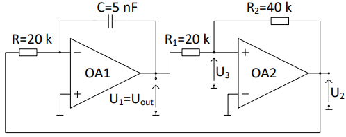
Acting as if your opamps are ideal comparators, yes, that's possible, so let's start you in the right direction (I'd have to calculate the whole equation myself, so, I'll let you do that instead :) ).
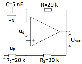
Looking at your upper schematic:
Assume that at t=0 the capacitor is charged to half the voltage across it is U_out, U_N = U_out /2. Logically, that's the same voltage as U_p, since R_1 and R_2 form a voltage halver. Therefore, u_d is 0 V at exactly that point. Prior, it had to be negative (since the capacitor was in the process of being charged), and later it will be positive.
Now, what happens the next instant, now that u_d becomes positive? The negative input of your opamp becomes higher than the positive: the output toggles to -U_out.
So, we have a capacitor still charged to U_out/2, connected via R to a potential of -U_out, so there's a voltage drop of 3/2 U_out across R.
Now, all you have to do is take the equation that describes the current flowing out of the capacitor through R in relation to the temporal development of the voltage across the capacitor; that's the fundamental equation of
$$I(t) = C\frac{\mathrm d\, V(t)}{\mathrm dt}\text,$$
which you only have to fill in with \$I(t) = \frac{V(t) -(-U_\text{out})}{R}\$, yielding
$$\frac{V(t)}R +\frac{U_\text{out}}{R} = C\frac{\mathrm d\, V(t)}{\mathrm dt}\text,$$
which is a differential equation in V(t), and the solution to it is the well-known "RC discharge" equation, with 3/2U_out being the initial voltage (for t=0),
$$V_N(t>0)= \frac32 V_\text{out} e^{-\frac{t}{RC}}\text.$$
You only need to find the point when u_d changes sign again (i.e. the \$t\$ when \$V_N(t>0) = \frac{-U_\text{out}}2\$ and tadah, ways to calculate your oscillation's period.


