1
\$\begingroup\$

I have a question about LED lamp:

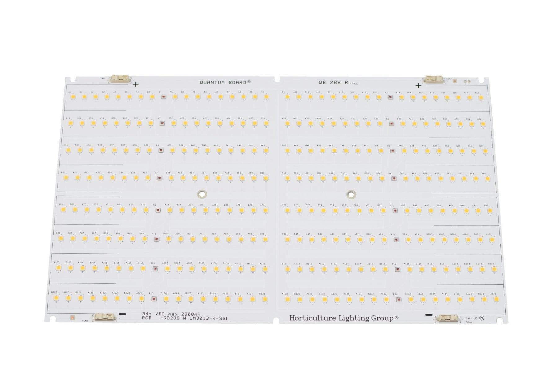
enter image description here Quantum Board

It has 16 strings of LEDs connected in parallel. Each string consist of 18 LEDs connected in series. It's supplied with constant current source (with max current 2800mA, what is much more than safe current for single LED/led string.) I know that connecting LEDs in parallel is not the best solution because of imperfection of LEDs while manufacturing and as a result inequality of currents through every string. But I see that is quite common solution for such lamps. I have several assumption how it is possible:

  • using LEDs with very similar parameters (Vf), using LEDs with same binning. But actually, according to datasheet Samsung LM301B leds have 1V of Vf variation even inside every binning group. Possible in practice this variation is much lower.
  • very good thermal dissipation due to metal-core PCB

Could anyone explain how does it works? Are my suggestions the keys for the answer? Is putting a series current limiting resistor for every string and using CV source a more robust solution and why not do it in this way?

\$\endgroup\$
2
  • 1
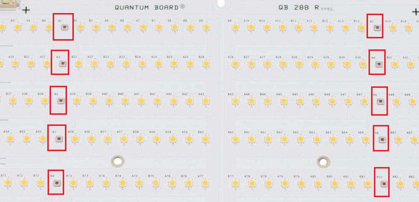
    \$\begingroup\$ Zoom in on the photo ... there are components with designator "R" in the middle of each string. I'll let you guess what they do. \$\endgroup\$
    – user16324
    Commented Jan 22, 2020 at 13:24
  • 1
    \$\begingroup\$ Definitely, not resistors. These are 660 nm leds, in this case "R" means "Red", I suppose \$\endgroup\$
    – plumbum_by
    Commented Jan 22, 2020 at 15:35

5 Answers 5

2
\$\begingroup\$

using LEDs with very similar parameters (Vf), using LEDs with same binning. But actually, according to datasheet Samsung LM301B leds have 1V of Vf variation even inside every binning group.

I think you missed a decimal place there? The AY bin LM301B LEDs is actually speced with a min/max Vf of 2.6 to 2.7V. That is a very tight spec, so the difference between individual diodes will be very small.

Could anyone explain how does it works?

The absolute maximum difference is very small, the average difference smaller still, and 18 diodes are put in series. If you take a small variation and average it 18-fold, you get an absolutely tiny variation between parallel strings.

For example, if you assume the average variation is 50mV, and averaging that 18-fold will reduce that to about 12mV, or about 0.02%. That is insignificant.

Is putting a series current limiting resistor for every string and using CV source a more robust solution and why not do it in this way?
If you bought a quantum board, you paid many times what a normal LED costs for a high efficiency diode with the lowest possible forward voltage so that you can save electrical power. Putting a series resistor to drop voltage would defeat the purpose of having spent that money.

\$\endgroup\$
2
  • \$\begingroup\$ Definitely yes. It should be 0.1V. Thanks for correction. \$\endgroup\$
    – plumbum_by
    Commented Jan 22, 2020 at 18:30
  • \$\begingroup\$ Great thanks for detailed explanation! \$\endgroup\$
    – plumbum_by
    Commented Jan 23, 2020 at 11:38
2
\$\begingroup\$

Look again: -

enter image description here

I see R1 to R10.

\$\endgroup\$
6
  • 1
    \$\begingroup\$ I'm betting the "R" stands for "Red LED" as these things definitely don't look like resistors, and the description mentions 16 red LEDs... \$\endgroup\$
    – bobflux
    Commented Jan 22, 2020 at 13:52
  • \$\begingroup\$ @peufeu it's a good spot and you could be right. The bigger picture is not to assume anything about a product whose details are scant at best. After all, who is to say what's on the underside of the board that might make a mockery of any assumptions? \$\endgroup\$
    – Andy aka
    Commented Jan 22, 2020 at 14:02
  • 2
    \$\begingroup\$ It's not resistors, it's 660nm deep red leds. In this case i'm sure there are no elements on bottom layer: it's aluminium PCB, adding bottom layer will increase cost, and will not allow to attach PCB to heatsink. This PCB even don't have vias and all elements are surface mount and it looks reasonable. \$\endgroup\$
    – plumbum_by
    Commented Jan 22, 2020 at 14:10
  • \$\begingroup\$ @plumbum_by What does the product specify should be used as a power supply? Are there more product details anywhere? It's usually the case that lack of product details can mean lack of product quality and so you can't really make generic design assumptions based on what you see in a product that might be somewhat lacking in quality documents. \$\endgroup\$
    – Andy aka
    Commented Jan 22, 2020 at 14:20
  • \$\begingroup\$ You can find more details via link: horticulturelightinggroup.com/collections/quantum-boards/… And it also is selling as a kit with Meanwell HLG-120H-54A constant current power supply horticulturelightinggroup.com/collections/kits/products/… \$\endgroup\$
    – plumbum_by
    Commented Jan 22, 2020 at 14:54
1
\$\begingroup\$

There are plenty of LED lamps that don't have current limiting resistors and rely on the LEDs being equal. This often is not a problem or not seen as a problem.

The LEDs might be "equal enough" for the current to divide itself properly. Maybe the current isn't exactly divided equally but as long as the difference in the current through the LEDs isn't too small or too large, the difference in currents is not a problem.

The LEDs themselves have some series resistance.

With many LEDs in series, differences in forward voltage will "average out" reducing the difference between LED strings.

Is putting a series current limiting resistor for every string and using CV source a more robust solution and why not do it in this way?

Indeed this would be a more robust solution to add current limiting resistors.

The reasons why this isn't always done might be cost (a resistor cost money and might take up valuable space where there could be an LED). Also: it works without resistors so why add them?

\$\endgroup\$
5
  • \$\begingroup\$ Space could be the reason, but resistor's cost... Resistor cost really nothing comparing with 288 samsung leds cost \$\endgroup\$
    – plumbum_by
    Commented Jan 22, 2020 at 14:18
  • \$\begingroup\$ @plumbum_by you're forgetting that the cost of a resistor isn't only the price of that resistor (which is indeed quite low) but the cost of having a resistor on the board or not having a resistor on the board. Adding an extra (different type) of component complicates things. When manufacturers try to squeeze out every cent, such small things do matter. \$\endgroup\$ Commented Jan 22, 2020 at 14:25
  • \$\begingroup\$ The reason no resistors are used is that quantum boards are designed for the highest possible umol/J photon efficiency. Buying very high efficiency LEDs and then wasting power in a resistor wouldn't make sense. \$\endgroup\$ Commented Jan 22, 2020 at 15:00
  • \$\begingroup\$ @user1850479 it sounds very reasonable, but i'm really confused about how current balance in parallel sections is achieved? \$\endgroup\$
    – plumbum_by
    Commented Jan 22, 2020 at 15:29
  • \$\begingroup\$ @plumbum_by See my answer for detailed explanation. \$\endgroup\$ Commented Jan 22, 2020 at 15:33
1
\$\begingroup\$

The LM301B has the spec, Vf=2.8V and If=200mA. The voltage on 18 LEDs in series is roughly 54V. If each branch has 200mA current, 16 of them will have 3200mA in total.

The current source you have sources 2800mA. So each branch will get 175mA (2800mA/16) on average, which is less then the spec of 200mA. Let's say one branch is broken open, the other branches will get 187mA (2800mA/15) each on average. Even two strings are broken open, the current on a average on each string is 200mA. So, it seems OK or normal operation as long as the LEDs are functioning and cooling is in place.

If you ask what would happen when three or more strings break open, or two strings break but variation of each component can cause some components operate outside of the spec, you are right, the design is not completely safe.

\$\endgroup\$
2
  • \$\begingroup\$ Calculating 2800mA/16 = 175 mA, you suppose that current in every branch wil be equal. But it will be not. LEDs are not fully equal due to manufacturing process and have some variation in parameters. It could be 201mA for one branch and 2800-201 = 2599 for 15 others. \$\endgroup\$
    – plumbum_by
    Commented Jan 22, 2020 at 18:55
  • \$\begingroup\$ That is true. That is why I considered two other cases with one or two strings open, which are worse than part to part variation. If you like, you can consider extreme part to part Vf variation, and see how much different current will you get for different stings under worse case condition, and you may see 5% variation. However, loosing one or two strings, the increase on other strings can be 10% to 20%. \$\endgroup\$
    – X J
    Commented Jan 22, 2020 at 19:10
0
\$\begingroup\$

As the others explained, if the LEDs are binned and everything is at the same temperature, it'll work.

However, with a constant current power supply, if one of the LEDs fails open the entire string will turn off and the current will be shared between the remaining strings, which will take more current. There are a lot of LED strings here, so this is much less of a problem than if you had only two LED strings in parallel (in which case one failed string would double the current in the other).

Your Meanwell PSU has a current setting, and also a voltage limit setting. So it is a good idea to measure the output voltage with the LEDs on, then unplug the LEDs. Without a load, the power supply will output its maximum voltage. Then adjust the "output voltage limit" potentiometer so that the no-load voltage is maybe a volt higher than the voltage when loaded by the LEDs. Then check again with the LEDs. This ensures even if a LED string blows open, and the PSU tries to output constant current, it will hit its voltage limit.

\$\endgroup\$

Your Answer

By clicking “Post Your Answer”, you agree to our terms of service and acknowledge you have read our privacy policy.

Not the answer you're looking for? Browse other questions tagged or ask your own question.