0
\$\begingroup\$

In a symmetrical and balanced three phase system no current flows on the neutral conductor.

Obviously the real electric power distribution systems are not perfectly balanced, so there is a current on it. But it seems to me like a parasitic effect, which is due to the fact that I connect devices which are different from those of other people etc.

But, at least in Italy where I live, we receive from the electric power distributors two wires which are the phase and the neutral (and this one is about at the earth potential). So, the neutral is designed to let the current flow on it (and so it is not a parasitic effect due to the fact that the load is not balanced). So, which is the role of the neutral conductor?

\$\endgroup\$
12
  • \$\begingroup\$ isn't it simply a return path to complete circuits and allow current to flow? \$\endgroup\$
    – vicatcu
    Commented Feb 16, 2020 at 14:52
  • 1
    \$\begingroup\$ @Kinka-Byo so, what do you think happens when you remove the neutral wire. Where would your current flow? I'm honestly a bit confused on which level you're asking this. How can you think the current through neutral is a "parasitic effect"? I think you're confusing a macroscopic view with your individual circuit. \$\endgroup\$ Commented Feb 16, 2020 at 15:29
  • 1
    \$\begingroup\$ @Kinka-Byo en.wikipedia.org/wiki/Three-phase_electric_power#/media/… Say, you are one of the Z_y, so I_1 flows from the generator labeled V_1 to ground. The wire coming from the generator is what is called "phase" or "live" in your installation, the wire going to ground "neutral". What would you do without that second wire?! \$\endgroup\$ Commented Feb 16, 2020 at 15:40
  • 1
    \$\begingroup\$ "we" don't say that. You claim that. It's not true. \$\endgroup\$ Commented Feb 16, 2020 at 16:18
  • 1
    \$\begingroup\$ @Kinka-Byo The neutral current in the combined neutral conductor is zero (In in your link). In your example the phase current is 5 A (3 x 5 A x 120 Vp-n = 1800 VA). So 5 A flows from each phase conductor into each load. 5 A returns from each load along its neutral conductor. If we measured the current in the short section of per-phase conductor from the load to the common neutral point we would read 5 A. Once the common point is reached the 3 return currents cancel each other out (because the vector sum of 3 equal currents at 120° to each other is zero) and no current is left to flow as In. \$\endgroup\$
    – Graham Nye
    Commented Feb 17, 2020 at 23:15

2 Answers 2

1
\$\begingroup\$

In a single phase system neutral and line wires provide a potential difference over the load that is to be powered. Neutral is commonly earthed, connected to the earth, at some point in your house. Because of this the neutral wire is at the same potential as the ground we are connected to making it typically less dangerous.

The connection between neutral and earth allows any phase-to-earth fault to develop enough current flow to "trip" the circuit overcurrent protection device.

wikipedia source

On a three phase system you can have a neutral wire but it is optional. Below are two three phase load configurations, Delta and Y. Neither requires a neutral conductor, though in the Y configuration neutral can be connected to the center, where all the phases meet. As you mentioned on a balanced three phase system no current flows through the neutral wire. In such a system current on the neutral wire can be indicative of a problem.

delta and y

It may help to visualize the waveform in polar coordinates. The radius is the same all around, indicating each phase magnitude is the same. Each phase is seperated by 120 degrees.
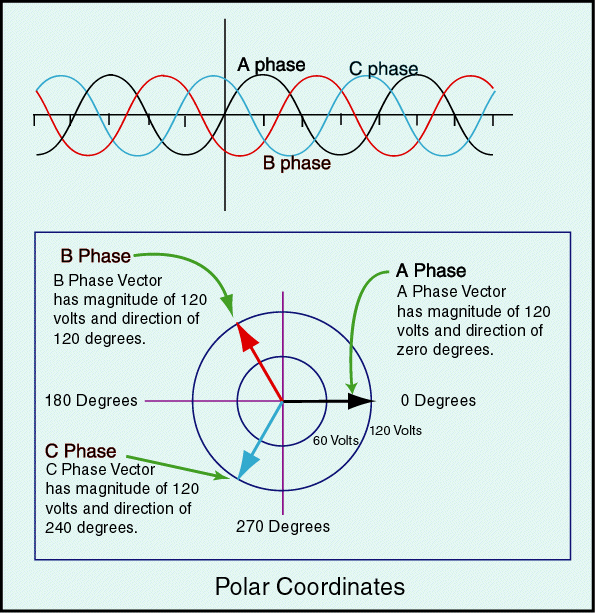
enter image description here

AC is always pusing and pulling current so it can be positive or negative at a particular instant. We can do a calculation to illustrate how a balanced 3 phase system would leave no current on the neutral phase.

  • A balanced system will have the same magnitude per phase (equal source and load), we can take that as 1.
  • A balanced system will have each phase seperated by 120 degrees.

So the following is true,

I_neutral = I_a + I_b + I_c

where I_x is the instantanious current at one time. Also if each phase is an ideal sine curve then

I = magnitude*Sin(theta)

where theta is the phase shift. So,

I_neutral = (1)Sin(0) + (1)Sin(120 deg) + (1)Sin(240 deg)
          = 0 + sqrt(3)/2 - sqrt(3)/2
          = 0 
  • As an aside, we talk about current and voltage in AC systems by using the RMS (root mean square) voltage or current; this is what a multimeter in the AC setting will read. This is not the peak volatage/current and not the average but the

value of the direct current that would produce the same average power dissipation in a resistive load -source

\$\endgroup\$
6
  • \$\begingroup\$ So, how can the current flow on my neutral, if ideally it should be 0? \$\endgroup\$
    – Kinka-Byo
    Commented Feb 16, 2020 at 19:24
  • \$\begingroup\$ On a three phase system, where there are in total 3 "hot" lines, if all phases are balenced then no current should be on the neutral line. If they are unbalanced then current will be dumped onto the neutral line. Ideally the AC phase voltage and current are like sine waves, each one offset from the next by 120 degrees. If each phase's load draws the same amount and the supply is ideal then as one phase pulls its max current the other two phases push the equal amount. \$\endgroup\$
    – jmb2341
    Commented Feb 16, 2020 at 23:16
  • \$\begingroup\$ If current is flowing on your neutral line in a Y configuration 3 phase system then the supply is not ideal or the load on one of the phases is drawing more than the others. So as the one phase pulls at its max the other two do not push enough to match and as a result current is seen on the neutral line. \$\endgroup\$
    – jmb2341
    Commented Feb 16, 2020 at 23:20
  • \$\begingroup\$ @Kinka-Byo does that answer your question? \$\endgroup\$
    – jmb2341
    Commented Feb 17, 2020 at 15:07
  • \$\begingroup\$ Mmm I have still my doubt. If, for an instant the load becomes balanced, I won't see current on my neutral... It seems strange \$\endgroup\$
    – Kinka-Byo
    Commented Feb 17, 2020 at 16:20
0
\$\begingroup\$

It depends of the connection. You could use each of three phase separately with neutral wire, or use "balanced three phase system".

\$\endgroup\$

Your Answer

By clicking “Post Your Answer”, you agree to our terms of service and acknowledge you have read our privacy policy.

Not the answer you're looking for? Browse other questions tagged or ask your own question.