0
\$\begingroup\$

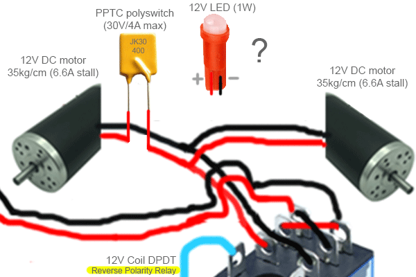
I have the following setup and it works well as is, except that I would like to protect the 12V DC motors (Reverse High Torque Permanent Magnet 12V DC motor) with a PPTC polyswitch + a LED to indicate a temporary overheating/blown state to the user.

enter image description here

I understand that by simply inserting the PPTC along the positive wire that goes to the DC motor will work. Tough, I would like some advice on how to additionally connect a 12V LED (1W) to that circuit.

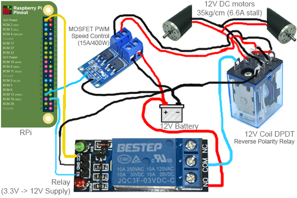
enter image description here

\$\endgroup\$
10
  • \$\begingroup\$ You haven’t said what you want the LED to indicate. And you haven’t linked the data sheet of the polyswitch. \$\endgroup\$
    – Andy aka
    Commented Feb 19, 2020 at 13:50
  • \$\begingroup\$ Uhm, yes I did? In the very first sentence? "+ a LED to indicate a temporary overheating/blown state to the user." / Also, for the datasheet, I guess just typing "JK30 400" in Google yields it? html.alldatasheet.com/html-pdf/565885/UNSEMI/JK30-400/217/1/… \$\endgroup\$
    – that-ben
    Commented Feb 19, 2020 at 13:56
  • \$\begingroup\$ I guess it was the how to additionally connect sentence that threw me. Are you happy that the forward volt drop of the polyfuse is acceptable for the motor in normal running. Wire the LED across the polyfuse if it has the correct rating for 12 volts and current limiting built in. Also add a reverse protection diode across the LED. \$\endgroup\$
    – Andy aka
    Commented Feb 19, 2020 at 14:05
  • \$\begingroup\$ "Are you" Yes. This DC motor (as you can see above) has a variable speed controlled by the user. That DC motor is rated for anything between 6V-12V. The voltage drop only means the motor will turn a little slower, but this is not critical. If I connect the LED across the polyfuse, then how will the circuit make a closed loop? I don't understand how this can work, since the PPTC is in series only on the positive wire. See above? Did you also read that the DC motor is bi-directional? So the red wire sometimes is negative, sometimes positive. \$\endgroup\$
    – that-ben
    Commented Feb 19, 2020 at 14:09
  • \$\begingroup\$ Use a bridge rectifier to feed the LED. The closed loop comes from the low dc resistance of the motor. \$\endgroup\$
    – Andy aka
    Commented Feb 19, 2020 at 14:27

1 Answer 1

2
\$\begingroup\$

Use a bridge rectifier to feed the LED. The closed loop comes from the low dc resistance of the motor. – Andy aka

Can you draw what you're discussing and put it in an answer?

Unfortunately I have no drawing facilities at the moment so I’ll try and describe...

Treat the voltage across the polyfuse as AC. Connect the polyfuse terminals to the AC terminals of a bridge rectifier. Connect the appropriate LED to the DC output of the bridge rectifier.

The LED you have chosen ought to be able to work down to 9 volts but, if it can’t then use a regular LED in series with a resistor.

\$\endgroup\$

Your Answer

By clicking “Post Your Answer”, you agree to our terms of service and acknowledge you have read our privacy policy.

Not the answer you're looking for? Browse other questions tagged or ask your own question.