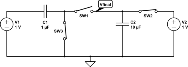
simulate this circuit – Schematic created using CircuitLab
The circuit has the initial condition as shown in figure. What will Vfinal be when SW3 and SW2 are open but SW1 is closed.

simulate this circuit – Schematic created using CircuitLab
The circuit has the initial condition as shown in figure. What will Vfinal be when SW3 and SW2 are open but SW1 is closed.
Both capacitors seem to have 1V, total 2V if put to series. They are connected in series with the 1V source, so a current starts. It's in practice finite and settles soon due the losses but the current is exactly the same for both capacitors. So, capacitors get equal amount (=X) of charge, obviously negative because their final summed voltage must be 1V. The voltage change is -1V. Calculate the X from the fact that -1V must be = X*(1/C1 + 1/C2). That's X divided by the total series capacitance.
Calculate the new voltages of the capacitors by adding to 1V amount X/C1 for C1 and X/C2 for C2.
BTW no charge vanishes when both capacitors get charge X and their series connection also gets X. That's because actually when one charges a capacitor the total charge change is zero. Charge +X to a capacitor means +X to one plate and -X to the other plate.
ADD: It can be simulated if the simulator allows one to set the initial capacitor voltages. Some loss resistance must be added to prevent division by zero. See here how the voltage of node 3 drops from 1V to about 0,91V. The loss resistor is huge to make the needed time range up to full second
The voltage of C1 (=v(2)-v(3) in the next simulation) drops from 1V to about 90 mV
The initial condition: $$Q_1=C_1U_1= 10^{-6}$$ $$Q_2=C_2U_2= 10^{-5}$$ $$U_1=U_2=1$$
The final state: $$Q=C_1\cdot U_1=C_2\cdot V_{final}$$ $$U_1+V_{final}=1$$
Solving the system: $$V_{final}=\frac{C_1}{C_1+C_2}$$
EDIT: See comments below the post to know why the following reasoning is incorrect.
Assuming the voltage source has internal resistance \$R\$, the voltages across the capacitors are given by:
\$v_{C1}(t) = \frac{10}{11}(1-e^{-t/RC}) + 1e^{-t/RC}\$
\$v_{C2}(t) = \frac{1}{11}(1-e^{-t/RC}) + 1e^{-t/RC}\$
where \$C = C1||C2\$
If you're any fan of superposition, a nice way to interpret above situation is to notice that the second term in each equation represents the exponential decay of initial voltage 1V on each capacitor. As you can see the initial charge on capacitors vanishes as \$t\to \infty\$, and wont matter for steadystate. (In reality, the charge doesn't vanish to \$0\$, it keeps decreasing and settles to a steady state value of \$10/11 \mu C\$)