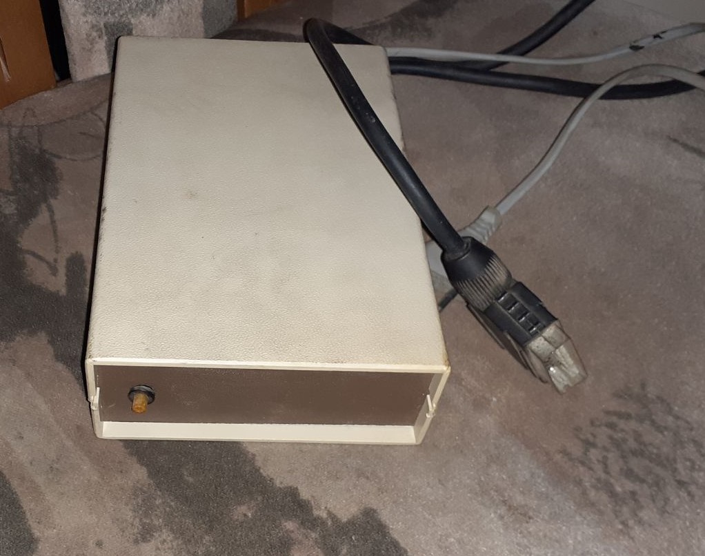
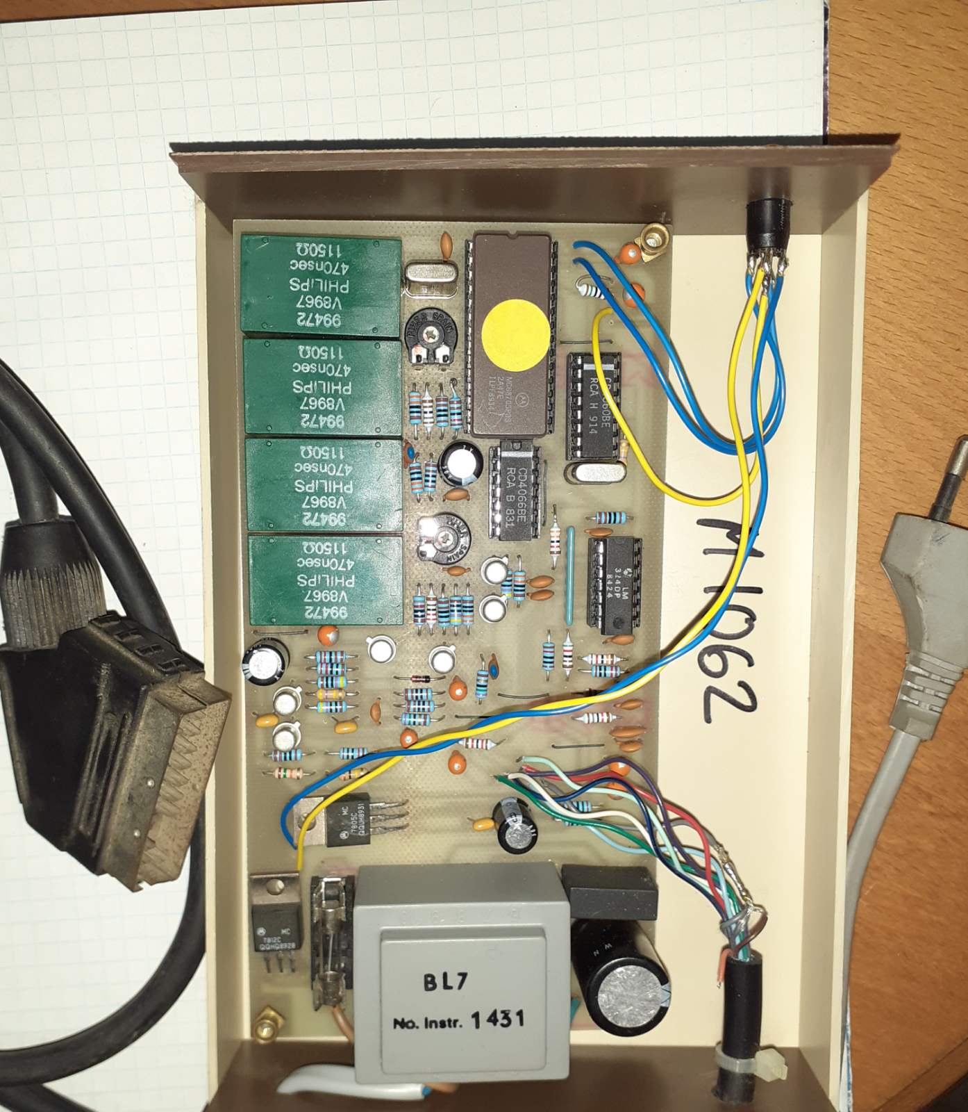
I found this device in my father's basement, but I can't figure out what this device is. It has only 1 SCART connector, 1 power cable and only 1 button in front of it. I think it may be some old video decoder, but I'm not sure. These are the images of the device outside, and the circuit board.
-
4\$\begingroup\$ Maybe a test-image generator? It's going to be next to impossible to figure this out without either a model number, or a schematic. \$\endgroup\$– Ron BeyerCommented May 11, 2020 at 20:18
-
1\$\begingroup\$ you should test which cables from the SCART connector are connected to the board. This will help. \$\endgroup\$– Marcus MüllerCommented May 11, 2020 at 20:48
-
12\$\begingroup\$ This is a vintage DIY Canal + decoder ! (Canal + is a French crypted TV Channel) \$\endgroup\$– andre314Commented May 11, 2020 at 21:15
-
1\$\begingroup\$ @winny Yes, pirate. \$\endgroup\$– andre314Commented May 11, 2020 at 21:35
-
3\$\begingroup\$ it is a large paper weight \$\endgroup\$– jsotolaCommented May 11, 2020 at 21:58
2 Answers
tl; dr: It’s an early Canal+ 'pirate' box (with props to commenters who mentioned that.)
The clue is the set of delay lines. Canal+ was originally based on a scrambling scheme called 'RITC Discret 1', that randomly manipulated video delay in increments of 902ns (0, 902, 1804ns). Four 470ns delay lines (those green Philips things in the photo) would give 1880ns or 940ns in the middle, so fairly close.
More about that here: https://en.wikipedia.org/wiki/Television_encryption#RITC_Discret_1
And here it is being discussed (in French): https://www.smartphonefrance.info/actu.asp?ID=12502
Anyway, so the job of the HC05 is to figure out the current Discret 1 keying based on a reference that's periodically broadcast, then implement the variable delay line-by-line, selecting one of the Philips delay taps.
What happened with this box? With the publication of the design in the December 1984 Radio Plans, it was widely produced, ultimately leading Canal+ to switch to a different scheme.
-
3\$\begingroup\$ Did the video signal go in and out through the single SCART connector using the pins 19 and 20 (composite video output / input)? Did satellite receivers have a dedicated SCART for such an external signal processing? \$\endgroup\$ Commented May 12, 2020 at 7:15
-
\$\begingroup\$ I wonder (also @pabouk) if it was used with some form of SCART splitter/adaptor cable. I still have a selection and I think I could combine them to get composite in and out of the same plug suitable for this \$\endgroup\$– Chris HCommented May 12, 2020 at 8:50
-
2\$\begingroup\$ @pabouk in Europe, SCART was pretty standard on any TV set after say 1993 or so, exactly because VCR and sat set-top boxes had it. Yes, SCART is a bidirectional thing: TV->VCR worked just as well as VCR->TV over the same cable; all pretty standard features! \$\endgroup\$ Commented May 12, 2020 at 13:28
-
\$\begingroup\$ Thank you very much! I think I remember now that it was used in some old Satellite TV configuration, when you have one antenna and multiple receivers. Sadly, today it can only be used for scavenging / spare parts. \$\endgroup\$– brkoCommented May 12, 2020 at 18:41
-
\$\begingroup\$ The "theory of operation" links point to domains that I assume expired. They currently link me to NSFW dating and cam sites... \$\endgroup\$ Commented Aug 26, 2021 at 1:33
The green rectangles appear to be delay lines, one IC is an analog switch CD4066BE, one is a quad op-amp chip LM324DP, the yellow sticker is a MC68705 microcontroller, and the right top IC is obscured in the image. I would assume the chip is mostly likely a switch like the CD4066BE. The power side of the system has what looks to be a step-down transformer (I couldn't find the datasheet) with a LM7805 which is a common voltage regulator IC to output +5vDC.
As for the function of the box, it was likely used for video like you suggested. Depending on the programming of the chip with the yellow sticker, it could be used for video decoding. However, it could also be used as a type of filtering box or signal generator because of the delay lines and op-amps which can be used as adders, subtractors, or oscillators (or more of course).
-
\$\begingroup\$ Does the yellow sticker covers up the window that is used for exposing the EPROM to ultraviolet light to erase it? \$\endgroup\$ Commented May 14, 2020 at 3:55
-
\$\begingroup\$ While I couldn't find the exact specification to reset/erase the EPROM, you can generally assume that the sticker covers the UV reset, yeah @JacobKrall \$\endgroup\$– nateCommented May 14, 2020 at 4:04


