1
\$\begingroup\$

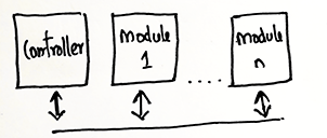
I'm looking to develop a modular IOT system which has a single master component and can be connected to multiple devices which can be used to turn on/off relays separately for my college project.

Block Diagram

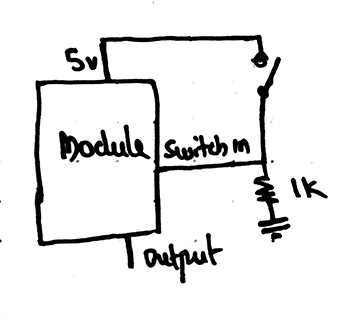
The main controller is managed by ESP32 is connected to an app via bluetooth. The app is updated with the state of every module and can turn on/off each module separately, each module can read or write to the controller, also each individual switches are rewired and connected to the module instead so that the relay inside the module can control the connected devices.

enter image description here

Here when the switch is turned on or off, the module writes to the main controller, so that it can take the state of the switch and update the app and also update the state of the device physically (this can either be done by the module itself). The modules are controlled by the controller sequentially, ie the first module which is connected to the controller gets updated first and so on. In the hardware i have added a shifting output which enables each module individually.

enter image description here

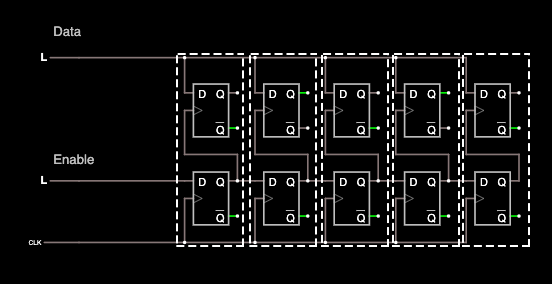
(This is just a simplified diagram of the shifting style communication that I'm trying to achieve, suggestion of any other method that aids in the end goal of not having to assign individual address for each module is appreciated)

The top and bottom D flip-flops are part of a module and initially the enable is left high while pulsing the first clock which puts the shift register into action. A bit can be set in the top D flip-flop which is the output of the module.

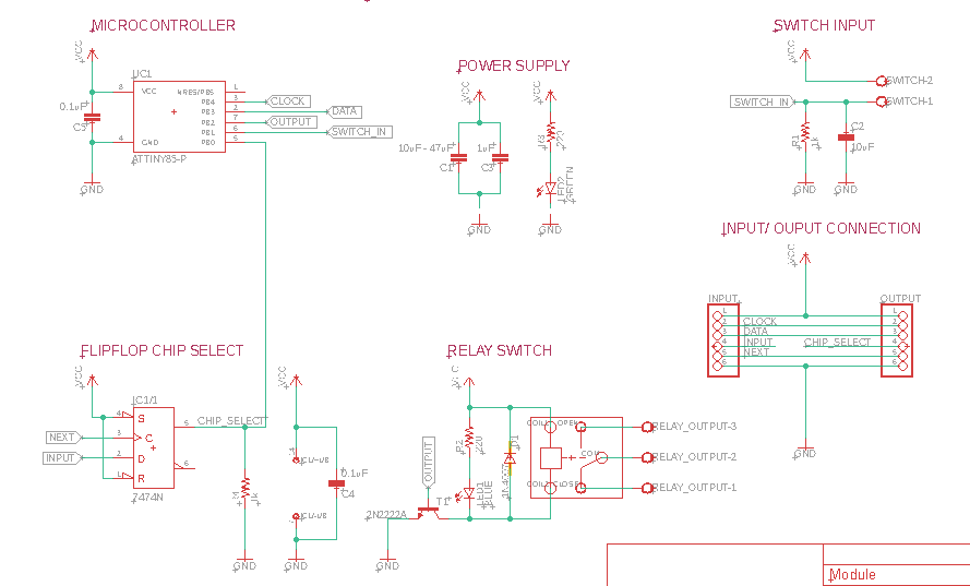
In my design I am using a microcontroller to control each specific module block. for more details I have added the modules schematic below.

enter image description here

(Here I am using an I2C style communication, after a chip has been enabled by the shifting output) It would be of great help if you can suggest a better and efficient alternative to create such a system.

\$\endgroup\$
0

2 Answers 2

1
\$\begingroup\$

Shifting I2C enable bits through a chain of modules is a smart way of achieving your goal of individually addressing devices without pre-assigning different addresses to each module.

You could eliminate the register by using the microcontroller instead. It looks like you would need a device with a couple more pins on it though - for the enable and clock signals

At the expense of more software complication, you could reduce the clock and enable signals to a single signal, with special signalling. You could send a long pulse to indicate an enable=true and clock=rising-edge simultaneously and then a short pulse to indicate just a clock rising-edge with enable=low. This would require 1 signal in and 1 signal out to the next module. You would then implement the I2C enable/disable in software rather than using a hardware pin connected to the I2C peripheral.

You might just want to keep it simple though :) For your coursework, I think the approach you have is already a good one.

\$\endgroup\$
0
\$\begingroup\$

Look into a protocol called DMX512. It was designed for stage lighting but can be used for just about any kind of simple controls. DMX uses a serial line with addressable components, linked in daisy-chain with RS-422/485. It's more rugged than I2C for long cable runs.

Even if you don't use DMX, at least it's a possible basis for a simplified version.

On the other hand I can't recommend I2C for anything other than a short run at a board level. Even its use for DDC in HDMI is limited (100KHz), and that's only for one load.

\$\endgroup\$

Your Answer

By clicking “Post Your Answer”, you agree to our terms of service and acknowledge you have read our privacy policy.

Not the answer you're looking for? Browse other questions tagged or ask your own question.