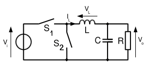
Ive been trying to find a mathematical explanation on how a Synchronous Buck converter maintains continuous operation under ideal steady state conditions. I understand the underlying concept but i want to know how i can explain it mathematically (ideal case).
-
\$\begingroup\$ if you're looking for an ideal case and not concerned about switching losses / behavior then its exactly the same as a regular buck converter except your 1-Duty cycle is now your on time for the lower switch instead of the diode path. every single equation would still apply, again ideally. \$\endgroup\$– Edwin FairchildCommented Oct 7, 2020 at 3:59
-
\$\begingroup\$ Could you please provide this explanation mathematically possibly ? \$\endgroup\$– jpg4321Commented Oct 7, 2020 at 4:35
-
1\$\begingroup\$ You can have a look at the answer I gave here. There is nothing mysterious, it is just that the controlled low-side switch keeps conducting while the inductor current is zero (the diode would spontaneously block) and brings the inductor current negative until the high-switch turns back on again. In a no-load situation, the inductor average current is zero and it peaks above and below ground. \$\endgroup\$– Verbal KintCommented Oct 7, 2020 at 6:13
1 Answer
This is the simplest and easiest switching converter to understand: -
The input voltage is modulated by the switch's duty cycle to produce an average value that corresponds with the required output voltage.
The LC acts as a low pass filter and converts the modulated duty cycle from above into a steady DC value.
There are mathematics involved if you want them to be but the words are simple enough and 100% accurate in defining the operation of two switches selecting either Vin or 0 volts.
If you want the maths of the LC filter then there are plenty of resources for this and a calculator to help you visualize things. The theory is not that involved so I've not bothered to repeat it here but, if you need it or help with it please ask.

