1
\$\begingroup\$

I have read about Series RC Circuit and have understood the Time constant concept.

Wikipedia states - "It is the time required to charge the capacitor, through the resistor, from an initial charge voltage of zero to approximately 63.2% of the value of an applied DC voltage, or to discharge the capacitor through the same resistor to approximately 36.8% of its initial charge voltage. "

Since Capacitor is charged through this resistor, the concept of time constant is valid.

But assume a parallel RC Circuit. I was not able to find the formula for time constant of a parallel RC circuit and also not sure whether the concept of time constant in a parallel RC circuit would mean something?

Can someone provide me the formula for Parallel RC Circuit during charging and discharging?

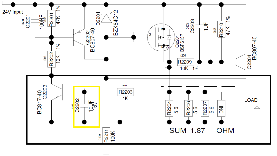
My question is based on the below circuit :

enter image description here

Once the voltage across the sense resistors cross 0.7V, the Transistor Q2203 will turn ON. What role does the C2202 play in combination with the sense resistors?

I have checked and reduced the value of C2202 in simulation and saw that if I decreased the value of C2202, the transistor turns ON quickly for a certain load resistance. If C2202 value is increased, the time taken for the Q2203 to turn ON increases? So, I thought of researching on charging of a parallel RC Circuit and its formulas which I couldn't find?

Please help me to solve my queries in the question.

\$\endgroup\$

2 Answers 2

2
\$\begingroup\$

If you apply Norton's or Thevenin's equivalent circuit theory, it'll be apparent that a series RC circuit is no different to a parallel one. The time constant is the same.

In your circuit, R2203, C2202 form a high pass filter. One presumes in that circuit to prevent 'nuisance operation' of the current sense.

Again, in answer to your question, apply Norton/Thevenin circuit analysis. You'll see that the 1.87 ohms is insignificant and the RC time constant of the sense circuit is 1k.10u or 10 milliseconds.

\$\endgroup\$
8
  • \$\begingroup\$ So, in my above circuit, to calculate the RC time constant, I should consider the 1.87Ohms and the 10uF value right? Could you please show the calculation of how you arrived at 1k, 10u and 100us? Please. \$\endgroup\$
    – user220456
    Commented Oct 8, 2020 at 16:05
  • \$\begingroup\$ The 1.87 ohms is insignificant. R2203 is 1k and C2202 is 10u. Rsense at 1.87 ohms completes the circuit. Being so tiny there's no need to add its value to R2203 in practice. If it were larger then we'd add Rsense to R2203 to find Rtotal. The time constant is R.C, which is 1k.10u = 10ms. Oops. I miscalculated before !. My brain must be playing tricks on me. \$\endgroup\$ Commented Oct 8, 2020 at 16:28
  • 1
    \$\begingroup\$ Clearly increasing C2202 increases the time constant, slowing down the response of the current limit. Do you need a worked example ? Q2203 needs about 0.6V Vbe to turn it on. If the instantaneous current in Rsense is ~530mA it will apply ~1V to the R.C network formed by R2203 and C2202. We know that the voltage developed in one time constant is 63% of the input voltage, i.e. 630mV (63% of 1V). So, after 1 R.C time constant (10ms) Q2203 will turn on and limit the current. Increasing the value of C2202 increases the delay. For DC the limit current will be ~0.6/1.87 (Vbe/Rsense) = 320mA. \$\endgroup\$ Commented Oct 8, 2020 at 16:47
  • 1
    \$\begingroup\$ In answer to your additional question, Rsense is purely the parallel value of R2204,6,7. It doesn't 'see' any meaningful capacitance. The voltage developed across it is applied to the base of Q2203 via R2202. C2203 across the base of Q2203 provides the C in the series R.C so formed. Remember that until it starts conducting the base junction of Q2203 is an open. Sadly many college/uni course 'overtheorise'. It may help to take a more pragmatic view. The tolerances on 'real world' components make a mockery of precise calculations. Save those for filter networks ! \$\endgroup\$ Commented Oct 8, 2020 at 16:57
  • 1
    \$\begingroup\$ Did you mean low-pass filter? \$\endgroup\$
    – Joe Mac
    Commented Oct 8, 2020 at 20:25
1
\$\begingroup\$

C2202 and R2203 form a single-pole low-pass filter. This sets the minimum rate of change of current through Q2201, the shunt resistors, and the external load. Note that rate of change across the cap will be slower than the rate of change across the load because of the gains of the three transistors in series.

The time constants of series and parallel R-C networks are the same. With a typical series network, resistor to V+ and capacitor to GND, the cap charges up to 63% of V+ in one time constant. If you maintain the connection for five time constants, the cap will be at 99% of V+. Now, if the resistor is switched from V+ to GND, the cap will discharge through the resistor. Again, the voltage across the capacitor will change by 63% in one time constant, only now the voltage is decreasing rather than increasing.

This is because a normal capacitor is symmetrical - charge flows into and out of it with equal facility.

\$\endgroup\$
4
  • \$\begingroup\$ Thank you for the answer. In your answer, did you mean Q2201 in place of Q2210? And when you say, "Note that rate of change across the cap will be slower than the rate of change across the load because of the gains of the three transistors in series." , - is it rate of change of current or rate of change of voltage? And how / which are the 3 transistors connected in series? \$\endgroup\$
    – user220456
    Commented Oct 8, 2020 at 16:24
  • \$\begingroup\$ How does increasing or decreasing the value of C2202 affect my current limiter circuit? \$\endgroup\$
    – user220456
    Commented Oct 8, 2020 at 16:25
  • \$\begingroup\$ In order : a) corrected; b) I should have been more clear: the rate of change of voltage across the cap affects the rate of change of current across the load; c) Q2201, 2202, 2203. \$\endgroup\$
    – AnalogKid
    Commented Oct 8, 2020 at 17:32
  • \$\begingroup\$ Increasing the cap value increases the R-C time constant, which will increase the effective time constant of the entire control loop. For a step increase in the load resistance, it will take longer for the circuit to adapt itself and increase the output current. \$\endgroup\$
    – AnalogKid
    Commented Oct 8, 2020 at 17:36

Your Answer

By clicking “Post Your Answer”, you agree to our terms of service and acknowledge you have read our privacy policy.