Question
How to design an alert system to do the following:
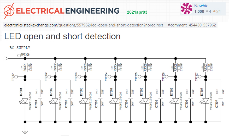
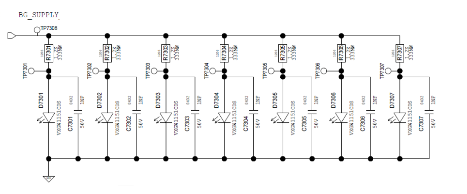
Detect if any one or more of the LEDs below are open or short circuited,
Report the bad LEDs, if any, and whwther they are open or shorted.

Answer
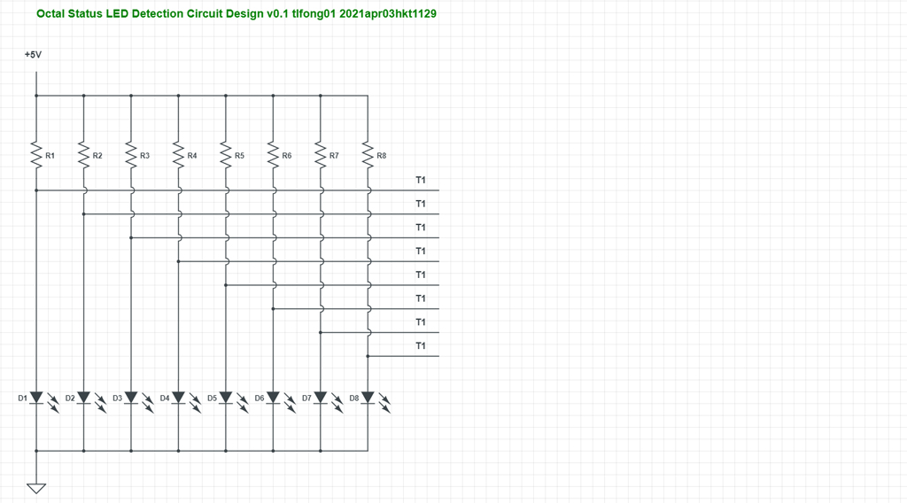
- To make things as simple as possible, the OP's specific circuit is abstracted and generalized below.

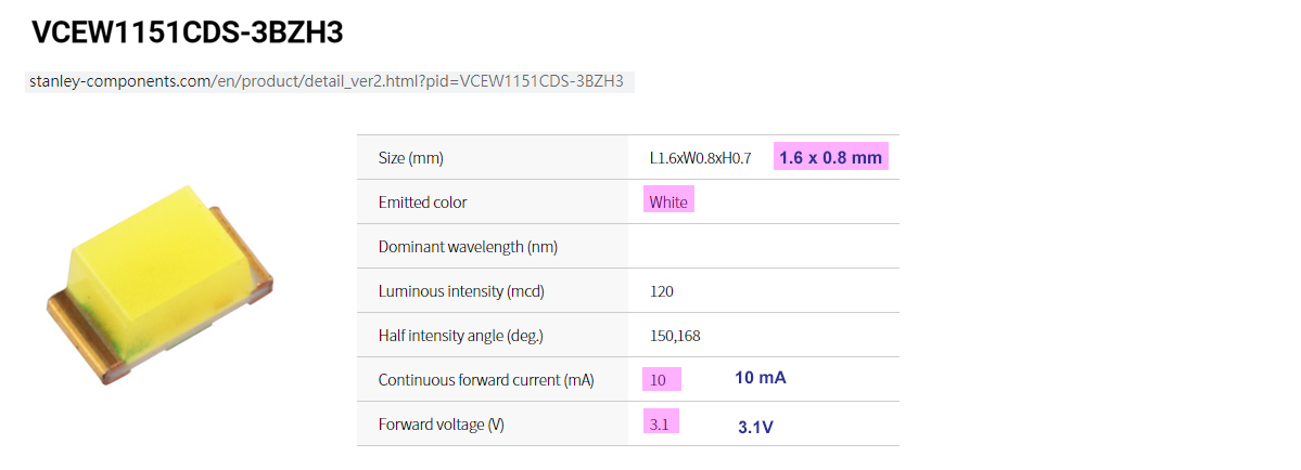
- But the OP's specific LED is not going to be generalized, but would be studied in detail, because the LED's specific I-V characteristic/parameters are critical in the circuit design.

LED Spec summary and assumption
The design parameters used would be the following:
2.1 Forward LED current I = 10mA
2.2 Forward LED voltage V = 3.1V
Power LED Lamps are usually of the power 1W or 3V, and current 350mA to over 1A. So I assume that the OP's LEDs are just typical indicator/status LEDs, though not in classical Red, but fashionable White.
I made another assumption that the Vcc is = +5V, as can be inferred from the current of limiting resistor of value 1k2.
What voltage level at the test points T1, .. T8 will be if a LED is open or shorted? This question is too simple, so I won't bother to explain, or my reputation would be damaged (But also see Appendix C )). Anyway, the following is a summary.
3.1 If a LED is open, corresponding test point would show approx 5V.
3.2 If a LED is shorted, it will be approx 0V.
In short, simply 5V TTL logic.
So the OP's problem boils down to simply the following:
How to read 7 TTL 5V logic High Low signals using 5V Arduino or 3V3 Rpi?
4.1 For 5V Arduio, it is a piece of cake: Just use 7 Arduino GPIO pins to direct read the High/Low levels at the 7 test points, and day is done.
4.2 For 3V3 Rpi (or similar 3V3 guys), a convert/shift down chip is need to setp down the 7 test points logical level to 5v to 3V3 (See Appendix A for more details). Then the 7 shifted down test point signals can direct connect to Rpi to read.
4.3 For either Arduino or Rpi, if there are not enough GPIO pins to go around, the OP can consider using GPIO pins extenders such are MCP23008 (See Appendix B for more details.)
References
(1) LED VCEW1151CDS-3BZH3 Product Sheet - Stanley
(2) CD4050 Hex Inverting Buffer and Converter - TI
/ to continue, ...
Appendices
Appendix A - Logical level signal up/down converter/shifters
For newbies, I would recommend the CD4050 Non-inverting Buffer/Logic Level down Converter.
There are many other logic level converts around, eg TBX/TSX 0102/0104/0106/0108.
Open drain NPN BJT, eg. 2N2222, MMPQ2222, HC03 Quad NAND logic ICs can also be used 3V3/5V0 up/down converters/shifters.
/ to continue, ...
Appendix B - GPIO Pins Expanders
Common GPIO pins expanders are I2C/SPI MCP3008/30017/3s08/30S17. But their learning curves are too deep for newbies.
For newbies, I would recommend I2C PCF8574 Remote 8-Bit I/O Expander, but the learning curve is still a bit high for newbies.
/ to continue, ...
Appendix C - Two Level or Three Level Logic Actually?
Let us look at the LED active/open/short voltage levels.
If the LED is open, no current can flow through the current limiting resistor (1k2), there is no voltage drop from Vcc = 5V. So the voltage at the test point is ~=5V.
If the LED is short circuited, the voltage across the LED is zero, so the test point is at the same level or ground, also ~= 0V.
But there is a catch here. At normal operation, according to the spec, current is around 10mA, and voltage across the LED is ~= 3.1V ~=3V
In other words, we have the Three Level Logic here: 0V, 3.3V, 5V. But GPIO pins can only detect two levels, Low level ~= 0V indicating LED is short, but High level may mean 3V ~ 5V. In other words, GPIO pin cannot differentiate between LED in normal operation, and open.
What should we do now? Comments welcome! :)
Hint: perhaps we might consider opAMP comparator, or Schmitt logic gate (eg, HC14 Schmitt inverter)


