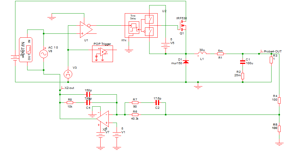
I made a simulation of a closed-loop buck converter with simplis.
the basic parameters of the open-loop circuit are listed below:
\$V_g=12V,V_{out}=5V\$
\$D=0.52\$
\$C=100\mu F,ESR=5m\Omega; L=30\mu H,ESR=5m\Omega\$
Then I made the compensation of the open-loop circuit.
The closed-loop circuit is this:
 I derived the both the ideal tf of the buck converter and the closed-loop tf.
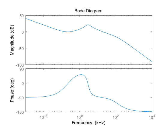
Using matlab, I got the ideal closed-loop bode like this 
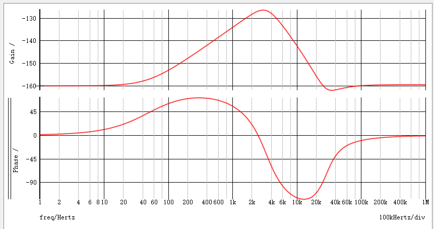
It is weird that when I build up the compensation circuit in simplis, the bode plot totally went wrong.
Neither the gain graph nor the phase graph suits the ideal bode plot of matlab.
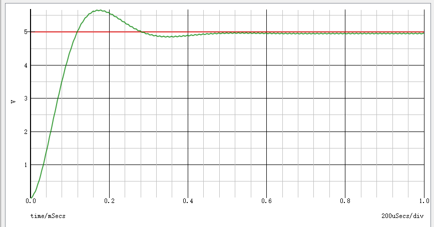
However the transient result looks good.
I think the derivation and the result of matlab are correct and there should be some mistakes in simplis simulation. I really appreciate your help if you can explain it for me.


