3
\$\begingroup\$

Why do RF signals on a microstrip/stripline require a ground plane to propagate within a circuit? When studying DC and low frequency AC circuits in school, it appears that ground is a particular point from which electrons are flowing, not a plane that provides any added benefit or relevance to the signal traveling forward on the line. Furthermore, why is it that we need coaxial, parallel plate, coplanar, etc. transmission lines in the first place, if a signal can travel down a conductor at low frequency without one?

Also, one more question that has been bothering me for a while. Why do we only care about reflections at high frequencies? Wouldn't low frequency signals see power reflected at impedance mismatches too? I understand that usually this is a question of line length compared to signal wavelength, but it seems that regardless of this, power should be reflected back.

\$\endgroup\$
6
  • \$\begingroup\$ I'm not sure if this helps, but imagine a very long hallway (it's a wire.) You have a sluice gate at one end. At the other end of the hallway is another hallway that is perpendicular to the first one (it's also a wire, but this is where the two meet/join (soldered or just a perpendicular trace.) Now, two cases: (1) Very slowly and gradually raise the sluice gate; or, (2) Very quickly open the sluice gate. In case (1), there will be barely any ripples at all when the water hits the connection point. In case (2), there will be a huge backsplash (reflection.) Crappy analogy, but maybe it helps? \$\endgroup\$
    – jonk
    Commented May 10, 2021 at 15:48
  • 1
    \$\begingroup\$ @jonk It's getting really frustrating to explain every single time why the comment section is not for answering OP's question. \$\endgroup\$
    – pipe
    Commented May 11, 2021 at 11:48
  • 1
    \$\begingroup\$ @jonk Why didn't you just write that as an answer? Please help me understand what makes that so difficult. Are you afraid of getting downvoted because you don't want to write a long answer? \$\endgroup\$
    – pipe
    Commented May 11, 2021 at 11:50
  • 1
    \$\begingroup\$ @pipe I've boxes of C64 equipment laying around here. Several C64s, printers, documentation, etc. It all needs a home. Interested? Look at my answers, whether recent or old, to see if any of them look like that comment I made above. None do. You can check. What I wrote above is just my prodding the OP to see what they are really asking about. I don't know and the OP hasn't helped me with a reply (or a response to anyone, for that matter.) If you were Voltage Spike, Russell McMahon, or SamGibson (moderators) perhaps I'd simply delete my comment. But I'll wait to hear from them. \$\endgroup\$
    – jonk
    Commented May 11, 2021 at 14:17
  • \$\begingroup\$ @jonk Nothing you wrote requires a response from OP to clarify the question other than replying "Thanks, that helped" without a way to accept the answer, leaving the question pending indefinitely. \$\endgroup\$
    – pipe
    Commented May 12, 2021 at 5:58

2 Answers 2

1
\$\begingroup\$

All signal propagation in circuits or through free space is finally happening as electromagnetic waves. The signal is NOT in the metal of wires, its in the electromagnetic field around the wires. The conductive wires only force the waves to travel to wanted directions.

Current in metal is a measurable side product that the EM field causes. Voltage is a scalar quantity which presents EM field in radically simplified way. Voltage and current together tell practically enough of the EM field at low enough frequencies and in a small enough circuit where one can succesfully assume that no waves exist and everything happens in the whole circuit at the same time.

But how high the frequency can be and how large can circuit dimensions be when one wants that ignoring waves doesn't cause too much error? No strict limit exists. But I would take propagating as waves into the account if the circuit width or length is 10% of the free space wavelength of the frequency.

If the frequency is 100MHz the wavelength in free space is 3 meters. That means I shouldn't ignore waves in a circuit which has biggest dimension 30 centimeters. Ignoring would cause so much error that nothing works.

The same experience has proved for me in practice that if the frequency is 100MHz and the biggest dimension of the circuit is only 3 centimeters (=1% of wavelength) I can well assume the signal propagates through the circuit in zero time and calculate the function of the circuit pretty well with Ohm's and Kirchoff's laws without substantial error. But the waves still exist. One can very likely detect with a radio receiver the small part of signal energy which jumps out of an unshielded 100MHz circuit (=radiates), no matter the biggest dimension of the circuit is only 3 cm. The 3cm size only makes small the error (in currents and voltages) caused by ignoring waves.

To make my 100 Mhz and 30 cm long circuit in perfectly predictable way I must design the wiring as transmission lines and take into the account how much phase lag is caused by the propagation time through the transmission line.

The simplest transmission lines are those which have 2 parallel wires. Twisted pair, coaxial cable and microstrip line belong to that category.

One wire transmission line exists. It's the Goubau-line. It needs not another wire.

https://en.wikipedia.org/wiki/Goubau_line
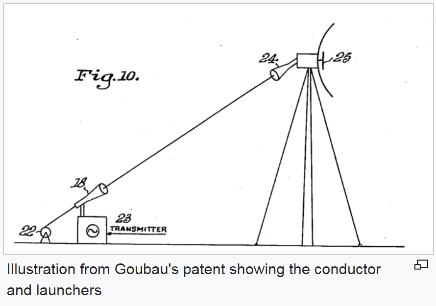
enter image description here

About reflections at 0.1Hz

There's an older answer which says it. You cannot have long enough distance to be able to measure the phase lag caused to 0.1Hz signal. In addition to generate and receive 0.1Hz practically detectable waves in free space with achievable voltages one would need say 300000 kilometres long antenna. Jupiter planet or the sun would be big enough reflectors to generate echos which have detectable power.

\$\endgroup\$
0
\$\begingroup\$

Microstrip and striplines were studied and characterized after solving Maxwell's equations in an infinite coaxial cable.

In that domain, if you treat frequency f as a fixed parameter, Maxwell's equations, provided voltage and current sources are purely sinusoidal, are solved in a closed form quite easy.

In a coaxial cable, the outer cylindrical conductor wraps the inner linear conductor.

Often, the outer conductor is called Reference Conductor or Ground conductor.


A stripline is derived from a coaxial cable where the outer conductor is opened and flattened to become a plane.

Often, the outer conductor is called Reference Plane or Ground Plane.


Reflections happen even when voltage or current sources are sine functions at a frequency 0.1 Hz.

To measure those reflections though you need conductors 10^9 km long.

\$\endgroup\$

Your Answer

By clicking “Post Your Answer”, you agree to our terms of service and acknowledge you have read our privacy policy.

Not the answer you're looking for? Browse other questions tagged or ask your own question.