Note: I have to thank you for asking this question, because it forced me to exercise my calculus muscles, which have atrophied after many years of disuse.
It's too easy to fall into the trap of modelling this circuit under the assumption that the transistor is a switch with negligible resistance, and the capacitor is simply being connected across a voltage source with negligible internal resistance. If this were true, then surely neither the transistor nor source would ever dissipate any \$I^2R\$ power. This same misapprehension leads to the "Two Capacitor Paradox" which you can read in this Wikipedia article.
In reality, there are a few sources of resistance, such as:
- The internal impedance of the source of \$V_{DD}\$
- The "on resistance" of the MOSFET
- The ESR of the capacitor
- The resistance of the all the interconnections
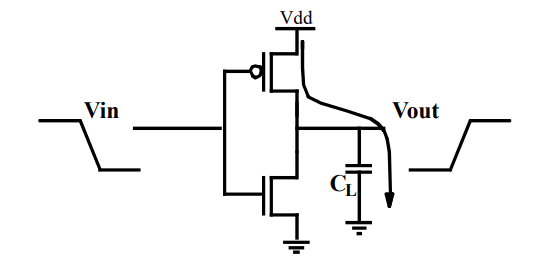
All these causes of impedance are not at all negligible, regardless of how close to zero ohms they are. The result is that the voltage across the capacitor cannot rise from zero to \$V_{DD}\$ instantaneously, because the current through it can never be infinite. In fact the graph of \$V_{OUT}\$ in your picture clearly shows a non-instantaneous slew from zero to \$V_{DD}\$, which is due to these resistances.
The fact is that during the transition of \$V_{OUT}\$, the transistor is a very real resistance, and the net result is that it will dissipate the same amount of energy as heat, as gets stored in the capacitor, which I will show here.
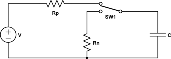
For our analysis we may assume that the dominant resistance is the transistor, with the voltage source and capacitor being ideal. To understand the consequences of non-zero transistor resistance, start with some basic observations about the circuit. Assuming the lower transistor is off, and can be ignored, the circuit consists of the upper FET and capacitor in series, across a power supply of \$V_{DD}\$. I will call the voltage across the transistor \$v_Q(t)\$, and \$v_C(t)\$ will be the voltage across the capacitor:
The current \$i\$ is the same in both the transistor and capacitor, by KCL.
The sum of voltages across the capacitor and transistor is \$V_{DD}\$, by KVL: $$ v_C(t) + v_Q(t) = V_{DD} $$
The capacitor is initially discharged: $$ v_C(0) = 0V $$
The capacitor is ultimately charged to potential \$V_{DD}\$: $$ v_C(\infty) = V_{DD} $$
The total power delivered to everything across the voltage source \$V_{DD}\$, at any instant \$t\$, is \$P_{A}(t)\$. Using the power rule \$P=I \times V\$:
$$ P_A = i \cdot V_{DD} $$
The instantaneous power delivered to the capacitor is:
$$ P_C = i \cdot v_C $$
The instantaneous power dissipated in the transistor is:
$$
\begin{aligned}
P_Q &= i \cdot v_Q \\ \\
&= i(V_{DD} - v_C) \\ \\
\end{aligned}
$$
We are interested in the amount of energy \$E_Q\$ delivered to the transistor, over the interval \$t=0\$ and \$t=\infty\$. Energy is integral of power, so:
$$
\begin{aligned}
E_Q &= \int_0^\infty P_Q \cdot dt \\ \\
&= \int_0^\infty i(V_{DD} - v_C) \cdot dt \\ \\
&= \int_0^\infty (i \cdot V_{DD} - i \cdot v_C) \cdot dt \\ \\
&= \underbrace{\int_0^\infty \underbrace{i \cdot V_{DD}}_{P_A} \cdot dt}_{E_A} - \underbrace{\int_0^\infty \underbrace{i \cdot v_C}_{P_C} \cdot dt}_{E_C} \\ \\
\end{aligned}
$$
If you examine those terms, the left term is an integration of total power \$P_A\$, which is total energy \$E_A\$ delivered by the the voltage source, and the right term is integrating capacitor power \$P_C\$, to obtain its stored energy \$E_C\$.
At this point you could replace the right term with the well known formula for energy in a capacitor, \$E=\frac{1}{2}CV^2\$, but for rigour, I'll continue as if we didn't know that. Anyway, \$V_{DD}\$ is constant, so this becomes:
$$ E_Q = V_{DD} \int_0^\infty i \cdot dt - \int_0^\infty i \cdot v_C \cdot dt $$
To proceed we need to address current \$i\$. The only thing we know about that is its relationship with capacitance \$C\$ and the voltage \$v_C\$ across it:
$$
\begin{aligned}
i &= C\frac{dv_C}{dt} \\ \\
\int i \cdot dt &= \int C \cdot dv_C \\ \\
\end{aligned}
$$
After a long time:
$$
\begin{aligned}
\int_0^\infty i \cdot dt &= \int_{v_C(0)}^{v_C(\infty)} C \cdot dv_C \\ \\
&= C \left[\vphantom{\frac{1}{1}}v_C\right]_0^{V_{DD}} \\ \\
&= C \cdot V_{DD}
\end{aligned}
$$
This is conviently constant, and we can substitute it into our equation for \$E_Q\$:
$$
\begin{aligned}
E_Q &= V_{DD} \int_0^\infty i \cdot dt - \int_0^\infty i \cdot v_C \cdot dt \\ \\
&= V_{DD} \cdot (C \cdot V_{DD}) - \int_0^\infty i \cdot v_C \cdot dt \\ \\
&= C \cdot {V_{DD}}^2 - \int_0^\infty i \cdot v_C \cdot dt \\ \\
\end{aligned}
$$
The energy stored in the capacitor is the integral over time of the power delivered to it. While the formula is well known, here's the derivation for this particular case. I had to refer to this SE answer, "Integral of the product of a function and its derivative", to get past the third line here:
$$
\begin{aligned}
E_C &= \int_0^\infty P_C \cdot dt \\ \\
&= \int_0^\infty i \cdot v_C \cdot dt \\ \\
&= \int_0^\infty C\frac{dv_C}{dt} \cdot v_C \cdot dt \\ \\
&= C \int_0^\infty v_C\prime \cdot v_C \cdot dt \\ \\
&= C \left[\frac{{v_C}^2}{2}\right]_{v_C(0)}^{v_C(\infty)} \\ \\
&= \frac{1}{2} C \cdot {V_{DD}}^2 \\ \\
\end{aligned}
$$
Plugging this into our equation for \$E_Q\$:
$$
\begin{aligned}
E_Q &= C \cdot {V_{DD}}^2 - \int_0^\infty i \cdot v_C \cdot dt \\ \\
&= C \cdot {V_{DD}}^2 - \frac{1}{2} C \cdot {V_{DD}}^2 \\ \\
&= \frac{1}{2} C \cdot {V_{DD}}^2 \\ \\
&= E_C
\end{aligned}
$$


