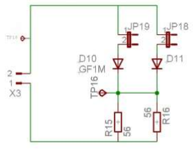
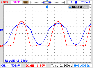
I've got a signal generator sending a sine wave to a PCB (X3). I closed jumper 19 so I measure D10, a GF1M diode. I measured the voltage over test point 16 (TP16) and the voltage over TP18. I get the following image on an oscilloscope. As expected we see that the voltage over TP16 is rectified (red CH2). The voltage over TP18 is an asymmetric sine wave (blue CH1). The width of the parts under 0 is smaller than the width of the parts above 0, but I don't understand why this is the case.
-
\$\begingroup\$ What is the output impedance of the signal generator ? What is the point of shorting the two cathodes of D11 and D10 ? \$\endgroup\$– citizenCommented Dec 2, 2021 at 8:33
-
\$\begingroup\$ Output impedance is 50 Ohm, JP18 is not closed in this case. It is shorted so the voltage over both diodes can be measured in TP16 whether JP18 or JP19 is closed. \$\endgroup\$– JonassoCommented Dec 2, 2021 at 8:41
-
\$\begingroup\$ Well in that case you do realise that R15 and R16 are in parallel with a total resistance of 28 Ohms for both diodes regardless of whether JP18/JP19 is closed ? What was the point of doing that ? Was that your intention ? \$\endgroup\$– citizenCommented Dec 2, 2021 at 9:56
-
\$\begingroup\$ The point of the experiment was to look at a diode's behaviour with a resistance in series. We need to explain why we're seeing the image on the oscilloscope. At TP16 it's clear to me, that the signal has to be rectified. However, I don't understand why the voltage on TP18 is an asymmetric sine wave. I believe it should be symmetric. \$\endgroup\$– JonassoCommented Dec 2, 2021 at 12:02
-
\$\begingroup\$ So this is a homework question after doing the experiment you need to write up your results, presumably with your lab partner ?? \$\endgroup\$– citizenCommented Dec 2, 2021 at 12:44
2 Answers
Think of the diode as conducting fully after the voltage across it exceeds 0,7V. This will then connect the "load" with the generator source and the voltage divider (resulting from the generator source impedance with the load impedance) will gradually kick-in for the positive part of the cycle (but with a diode exponential type gradual increase). Then for the negative going cycle, the diode is switched off and there is nothing loading the source, and the sine wave looks all perfect and symmetrical during the negative cycle, as one would expect.
-
\$\begingroup\$ Exactly what I needed, thank you! \$\endgroup\$– JonassoCommented Dec 2, 2021 at 16:30
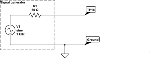
Consider your circuit when both bridges are open:
simulate this circuit – Schematic created using CircuitLab
You will see a sine wave at full amplitude at TP18.
Now consider what happens if you connect R15 between TP18 and ground:
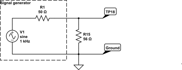
R1 (the internal 50 ohm impedance of the signal generator) forms a voltage divider with R15. This reduces the amplitude of the signal as measured at TP18.
Now consider that you have a diode between the signal generator output and R15. The resistor is effectively only there when the sine wave is positive.
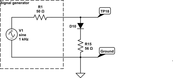
Does it make more sense now?
-
\$\begingroup\$ Yes, this is clear to me, thank you! \$\endgroup\$– JonassoCommented Dec 2, 2021 at 16:29

