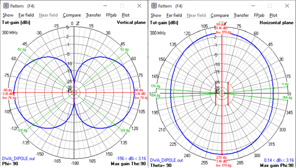
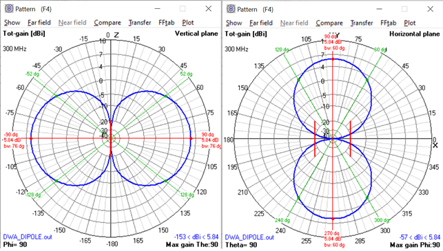
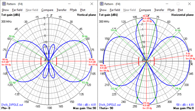
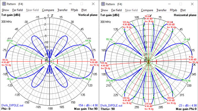
Because for spacings greater than lambda/2, you start to get grating lobes. These are the smaller lobes that show up away from the main axis of the beam, + and - 90 deg in these plots.
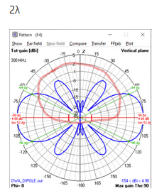
The grating lobes are at ~ -35 deg, + 35 deg, -145 deg, and + 145 deg.
These grating lobes take energy away from the main lobe and so reduce the gain of the main lobe. They don't come for free, and are usually undesirable in scanned array antenna systems.
Why do sidelobes appear?
Because when you combine energy from multiple antenna elements, the gain is greatest in the direction where the incoming energy is in phase when the two (or more) elements are combined. With separations greater than lambda/2, there are 2 (or more, depending on the spacing between the elements) directions in which the incoming energy is at the same phase - phase coherered is a term that's sometimes used. It's a modulo 180 deg phase thing. Hence the lambda/2 (180 deg) restriction for grating lobe free performance across the scan volume, -90 deg to + 90 deg, or - 180 deg to 0 deg in these plots.
There have been numerous posts here on this topic. Look for questions with tags like "antenna array" or "phase array". For example, look at my response here: how to understand grating lobe problem in broadside array

