0
\$\begingroup\$

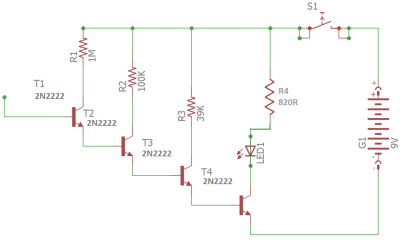
I build the schematics from https://hackaday.com/2022/01/10/a-simple-emf-detector-and-electroscope-you-can-make-from-junk-box-parts/ but the led stays on all the time on.

Why? What could be the cause of that?

enter image description here

Note: I considered the R4 820R enter image description here as resistor with 820 OHM. I hope I was correct.

\$\endgroup\$
6
  • 1
    \$\begingroup\$ How do you know the LED stays on? What if it flickers at mains frequency but you did not realize it? \$\endgroup\$
    – Justme
    Commented Jan 21, 2022 at 11:40
  • \$\begingroup\$ Maybe you are just in an EM field which triggers it? Have you tried to troubleshoot with a multimeter? \$\endgroup\$
    – vaizki
    Commented Jan 21, 2022 at 11:42
  • \$\begingroup\$ Open collector? Also those resistor values are silly high. Uh, but the LED cannot be on unless you supply it from somewhere. If the switch is NO then where is the LED supplied from? \$\endgroup\$
    – Lundin
    Commented Jan 21, 2022 at 11:42
  • 1
    \$\begingroup\$ @Lundin That's a de facto circuit for detecting live mains wire via capacitive coupling. \$\endgroup\$
    – Justme
    Commented Jan 21, 2022 at 11:52
  • \$\begingroup\$ @Justme Very good point. I should go far away from any source of EMF... \$\endgroup\$
    – Alex
    Commented Jan 21, 2022 at 13:55

2 Answers 2

8
\$\begingroup\$

Why? What could be the cause of that?

  • The 2N2222 collector leakage current is 10 nA.
  • So, T1 might be presumed to deliver 10 nA to T2's base.
  • This gets amplified by T2's beta (about 100) to 1 μA.
  • That gets delivered to T3's base which also amplifies it by 100 to get 100 μA collector current
  • T3's 100 μA feeds T4's base
  • T4 amplifies that by 100 to produce 10 mA through the LED.

enter image description here

It doesn't surprise me that the LED stays on all the time.

\$\endgroup\$
2
  • \$\begingroup\$ I agree completely with the conclusion, but doubt some of the calculation. Expecting a beta of 100 from a 2N2222 with a collector current of 1uA is at best optimistic - something like a 2N2484 might manage it. \$\endgroup\$
    – user131342
    Commented Jan 21, 2022 at 12:40
  • 3
    \$\begingroup\$ @henros I also assumed beta was 100 and, it might be more like 200 at the optimized collector current (maybe 10 mA) so, a few swings to the left are broadly countered by a few swings to the right and, maybe the LED has only 1 mA flowing. 1 mA is enough to make most LEDs look quite bright. The bottom line is that the hackaday circuit is pretty crappy hence why they use the term "hack" in their title. \$\endgroup\$
    – Andy aka
    Commented Jan 21, 2022 at 13:12
2
\$\begingroup\$

The collector cut-off current of 2N2222 is max 50nA at 50V. At the given Vcc 9V, it will be several nano amperes.

In your schematics, T2 - T4 are Darlingon-paired in sequense. At room temperature, hfe of 2N2222 is 150.

Thus, LED current can be calculated as

$$ I_{LED} ~= I_{CES} \times h_{FE} ^ 3 $$

This is enough to turn on normal LEDs, which turns on with a few miliamperes.

\$\endgroup\$

Your Answer

By clicking “Post Your Answer”, you agree to our terms of service and acknowledge you have read our privacy policy.

Not the answer you're looking for? Browse other questions tagged or ask your own question.