3
\$\begingroup\$

I'm making an Arduino Nano board for my project and can't figure out the capacitors for the crystal. While the equation may seem simple, i cannot find the stray capacitance and the load capacitance according to the data sheet for my crystal (X322516MLB4SI) is lower than the original Arduino Nano crystal.

If i assume the stray capacitance is 2 and the load capacitance according to LCSC is 9, i get capacitor values of 14pF.

  1. Is this a reasonable number or am i completely off?
  2. If I'm off by for example 5pF, how much of an impact does that have on the crystal? Is it a very small error like 0.01Mhz or can it go several Mhz off?

I will be using the boards for RS485 communication with a home-cockpit, nothing faster than 250Kbps.

\$\endgroup\$

2 Answers 2

3
\$\begingroup\$

The web page you linked also has a data sheet link but, the data sheet isn't particularly helpful at figuring out the load capacitance. At that point (and seeing contradictions between the seller's web-page and poor documentation in the data sheet) I would look elsewhere for a crystal.

However, if you trust the web page it specifies a load capacitance of 9 pF and that usually means 18 pF on one crystal pin to ground and 18 pF on the other crystal pin to ground. Clearly you should take into account the stray capacitance but, you would need to know what the input port's capacitance is; this will be the dominant modifier and it might be in the realm of 2 to 5 pF. I'm not going to guess.

If I'm off by for example 5pF, how much of an impact does that have on the crystal? Is it a very small error like 0.01Mhz or can it go several Mhz off?

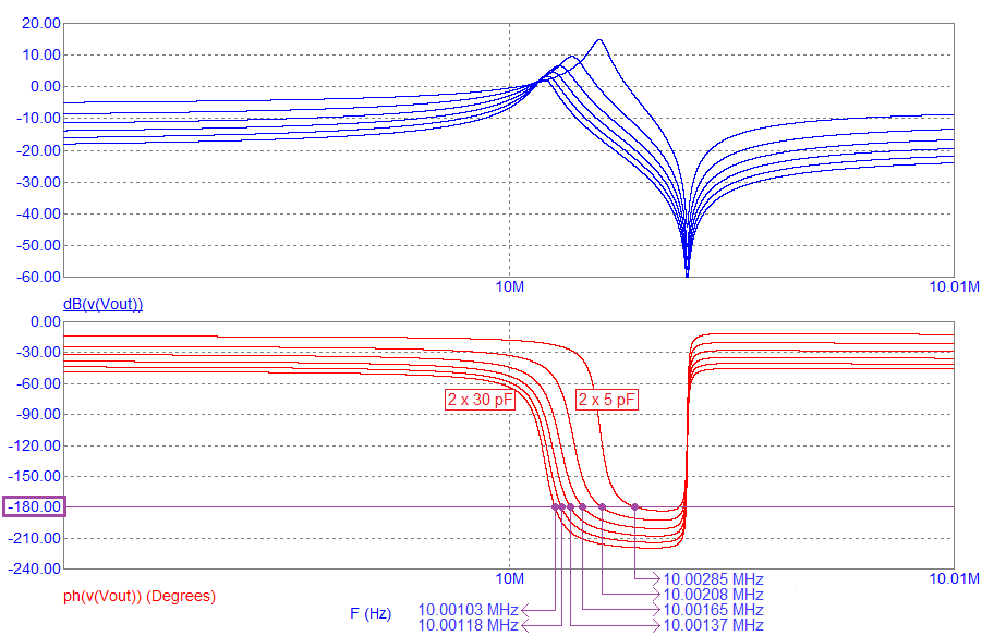
It won't drastically affect the operating frequency. For instance, this picture (from my very basic web site) shows a typical 10 MHz (series resonance) crystal and how much oscillation frequency might shift with quite drastic changes in loading capacitance: -

enter image description here

  • For a load capacitance change of 2 × 5 pF to 2 × 30 pF, the oscillation frequency moves about 2 kHz or 182 parts per million.

  • This is excessive compared to maybe having a crystal optimized for 2 × 10 pF and fitting 2 × 15 pF (43 ppm).

\$\endgroup\$
2
  • \$\begingroup\$ Thank you for the very detailed answer! So at the end of the day, for my use-case i can just put the 16pF caps there and call it a day? \$\endgroup\$ Commented Aug 19, 2022 at 10:02
  • 1
    \$\begingroup\$ I think it would work fine with 2 x 16 pF for RS485 comms providing you are using UART type transmission of data (i.e. single bytes with a start and stop bit) @MaciejSwic however, if you are using long sequences of data without start or stop bits (aka synchronous data) , you may have problems. \$\endgroup\$
    – Andy aka
    Commented Aug 19, 2022 at 10:05
1
\$\begingroup\$

The data sheet is generic for a whole series of crystals, not a specific orderable item, so the datasheet has no specific load capacitance values, it just tells you what kind of parts are available in this series.

The web page is for a specific orderable product in the series, with 9pF of load capacitance rating.

In theory and without stray capacitance, it would require 18pF capacitors.

The ATMega328P you seem to be referring to, suggests a range of 12 to 22 pF capacitor values.

This translates to a crystal with 6pF to 11pF load capacitance.

Based on this,

  1. Your selection of crystal with 9pF load seems to be within limts, and thus the 14pF capacitor value seems reasonable and within limits, but no one can determine if you have propery approximated the stray capacitances that are due to AVR IO pin and PCB trace capacitances. But it is quite close to the minimum capacitor value of 12pF, so it might be safer to select a crystal with higher load capacitance so you can use capacitors in the middle of the allowed range. On the other hand, the 6-11pF crystal range does not include the effect of stray capacitances so it is actually slightly larger.

  2. The error is generally so small that for UART comms which tolerate easily up to 1-2 % of tolerance it should not matter. In place of a crystal even a ceramic resonator should work, but crystal is more accurate. If you are worried about how much stray capacitance variation affects the crystal frequency, there i a calculatable term called pullability. In short, it means that the higher load capacitance and thus the higher capacitor values are used, the less the stray capacitance and variation affects the frequency. But due to this AVR model limiting the capacitor value to 22pF, if you choose that value, the crystal load requirement should be slightly higher than 11pF.

In the end, stray capacitaces may be approximated o even calculated from PCB layout, but in practice, you should measure the crystal frequency and adjust the capacitor values up or down to adjust the frequency. In practice, the frequency might not matter much as it is more important that the crystal circuit starts up and runs reliably and repeatedly, and has no problems starting up or running properly.

\$\endgroup\$
0

Your Answer

By clicking “Post Your Answer”, you agree to our terms of service and acknowledge you have read our privacy policy.

Not the answer you're looking for? Browse other questions tagged or ask your own question.