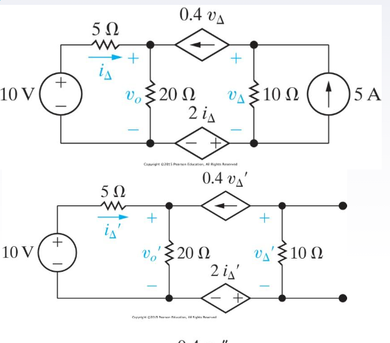
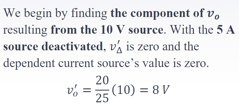
Segue
I've already explained in comments about a point of view I could suggest that is congruent with your quoted source. But you then write:
Won't the current from the voltage with the 2idelta' value below not
pass through the 10 ohm resistor? And because of that we will find new
voltage value on the right top?
Your question is apt. And it motivated me to write because the answer to your question is actually interesting.
The current in the dependent voltage source is easy
The current in the dependent voltage source, the one whose voltage is \$2\cdot i_\Delta\$, is easily computed.
Since you don't have part numbers in your schematic and if I don't assign them then I can't even talk to you, I am forced into laying out the schematic myself.
(Let this be a lesson to use the schematic editor and not to take the easy way out when asking questions by just pasting pictures.)
Here it is:
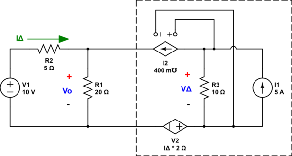
simulate this circuit – Schematic created using CircuitLab
(We are going to analyze the stuff within that box over on the right. I'm sure you agree that the current in and out of that two-terminal box must be equal.)
You can trivially determine the current in \$V_2\$. Let's assign ground as shown here:
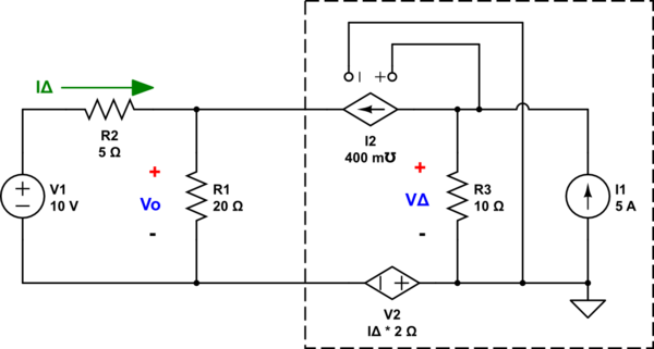
simulate this circuit
Look at the KCL for \$V_\Delta\$: \$\frac{V_\Delta}{R_3} + 0.4\:\mho\cdot V_\Delta= 5\:\text{A}\$. This instantly solves out to \$V_\Delta=10\:\text{V}\$.
There is \$1\:\text{A}\$ in \$R_3\$ and all the rest must be going out through \$I_2\$. And so the current in \$V_2\$ must be the difference between the current in \$R_3\$ and the current source \$I_1\$. Everything is already determined by \$I_1\$, \$I_2\$, and \$R_3\$. And nothing can be changed there.
So we now know the following:
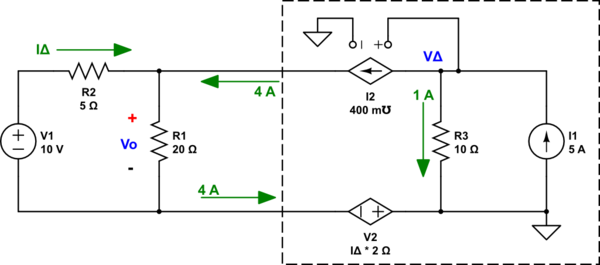
simulate this circuit
It won't matter where you put ground, either. You can place it elsewhere and that may complicate this analysis a bit. But you will get the same result.
So where next?
We can now reduce the circuit further by just moving the ground around (remember, only one node can be ground; but any node can be ground):

simulate this circuit
This solves out to \$V_{_\text{O}}=24\:\text{V}\$, \$I_\Delta=-2.8\:\text{A}\$, and \$V_{\Delta\text{( - )}}=-5.6\:\text{V}\$.
Do take note here that both \$V_{_\text{O}}\$ and \$V_{\Delta\text{( - )}}\$ are voltages relative to the new ground placement. I moved the ground to make things easier. I can do that.
Plugging all this back into the original schematic, but returning the ground back to where I earlier had it (and adjusting the just-made calculations accordingly), we find:
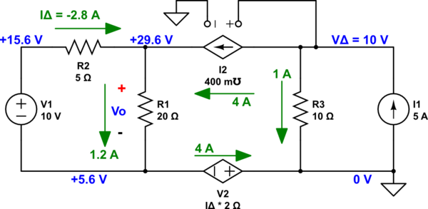
simulate this circuit
Now, recall my earlier warning when I moved the ground to make things still easier? I said to take note here that \$V_{_\text{O}}\$ is a voltage difference across \$R_1\$? Well, this is when you need to remember this, again. We do still have a \$24\:\text{V}\$ difference across \$R_1\$. But because I moved the ground back to a different node than when that difference was calculated, the two ends of \$R_1\$ are at different voltages with respect to ground. But the situation is still unchanged.
You are free to choose a different ground reference. But it won't change the currents in any way or the voltage differences between the nodes.
Here's an LTspice run of the above schematic:

Confirmed!
Summary to your question
I didn't directly solve your problem using the methodology your question suggests. But I don't have your textbook or class or the larger context. But I definitely could address the question you asked in comments. So I did.
Here's the curious thing. You don't need to care about the current in \$V_2\$! In fact, you can analyze everything without even caring about it. You could just set it to any arbitrary value, say \$0\:\text{A}\$, and so long as you don't write equations depending on it you will have enough information elsewhere to solve the circuit.
Sure, it's there. But it's just not important in this case.

