I have a schematic with LEDs. Let's say every LED takes 1.85 V and 20 mA. I want to find a resistor with the same resistance as the LEDs. How do I use Ohm's law?
1.85 / 0.02 * 6
or
(1.85 * 2)/(0.02 * 3)
and why?
I have a schematic with LEDs. Let's say every LED takes 1.85 V and 20 mA. I want to find a resistor with the same resistance as the LEDs. How do I use Ohm's law?
1.85 / 0.02 * 6
or
(1.85 * 2)/(0.02 * 3)
and why?
LEDs are not resistors.
Ohms Law was originally written for metallic conductors, and other components that have an essentially constant resistance, in other words, a behaviour than can usefully be called a constant resistance.
LEDs are more closely related to constant voltage devices, ie better modelled by a constant voltage in series with a very small resistor. If they conduct 20 mA at 1.85 V, they may well conduct uA at 1.75 V (very dim indeed), and amps at 1.95 V (gone up in smoke).
Your power supply voltage of 3.7 V suggests you are contemplating using a lithium ion battery with a nominal voltage of 3.7 V. In service, such a battery will deliver 4.2 down to 3ish volts, depending on where you stop discharging. Not a good power source for LEDs without current control.
To power LEDs successfully from such a source, use a LED plus resistor in series. With the nominal 3.7 and 1.85 V, you have 1.85 volts left across your current control resistor. Use a resistance of 1.85/20m = 93 ohms, or a few hundred ohms for controlling the current down to a friendlier 10 mA or so.
The best way to power LEDs is with a constant current supply. A series resistor is a reasonable approximation to a constant current, but it wastes a lot of power. This is not a problem for a single 10 mA indicator LED on an instrument, but in a lighting installation of many watts, designers will specify switch mode constant current supplies to avoid wasting 50% of their input power on heat in resistors.
To address your question directly, you have 60 mA being drawn from a 3.7 V source, so the equivalent load resistance would be 3.7/0.06 = 62 ohms, which happens to be an E24 standard value.
Shown below is a randomly-selected red LED where I vs. V has been plotted. This plot would likely be done at one temperature. Be aware that temperature affects LED voltage axis.
At the data point where 20mA flows, this particular LED requires about 1.8V. This might lead you to believe that its internal resistance is 1.8V/.02A which is 90 ohms. THIS IS WRONG as others have pointed out, because LEDs have non-linear internal resistance.
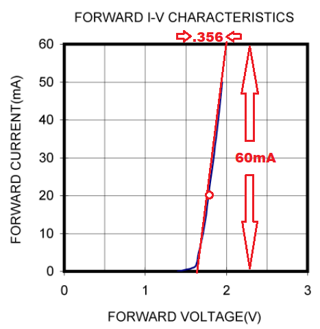
Shown in red is the slope of the curve tangent to the 20mA point. This slope allows you to calculate the LED's dynamic resistance.... \${0.356V} / {.06A} = 5.933 ohms\$.
Now suppose you connect this bank of 3 series-connected LEDs to a 3.7V battery. Since the LED's voltage add up to 1.8V + 1.8V = 3.6V, the remaining 0.1V would appear across the LED bank's dynamic resistance of 3.955 ohms. This would cause a current to be pulled from the battery of 0.1V/3.955= 25.28 mA....each LED would see one-third of this current...8.428 mA.
I have not accounted for the battery's internal dynamic resistance, which would cause even less current to flow.
Battery voltage would have to rise to at least 3.8373V for each LED to see 20mA. The 60mA flowing from the battery would cause \$.06\times 3.955= 0.2373V\$ drop across the LED's dynamic resistance. At this operating point, each LED voltage is 1.8V, so that battery voltage would have to be \$2\times 1.8+0.2373 = 3.873V\$
You should be able to see that the very small dynamic resistance affects greatly how much current will flow from a 3.7V battery. If it is freshly charged, much more current will flow than you expect, and if it is nearly discharged, very little if any current will flow. (Brilliance of LED optical output is proportional to current).
LEDs do not have specified resistance. They are nonlinear components. A LED may have nominal voltage 1.85 V and nominal current 20 mA, but it doesn't have resistance (1.85/0.02) i.e. 92.5 Ω. If you connect a 92.5 Ω resistor to 1 VDC the current will be 11 mA. If you connect the mentioned LED to 1 V the current probably is much lower due the nonlinearity - Ohm's law isn't valid for semiconductor components.
But you can calculate which resistor would sink total 60 mA from 3.7 VDC; that's 62 $ohm;.
Not a slightest idea what would be the current taken from your 3.7 V source if you build (and remove the rightmost, obviously accidental short) the drawn circuit and use 6 LEDs which are nominally 1.85 V and 20 mA. It may work or smoke. I would bet the latter. LEDs aren't identical and when one LED gets hotter than others the imbalance can grow in your circuit. The imbalance can grow so much that some LEDs are destroyed. To ensure predictable currents some resistor or a current regulator should be added to each of the three columns. Or you should use LED lamps which have the needed extra parts included.
It would be the voltage across the LEDs divided by the total current. The voltage is 3.7 V, the current in each series string of LEDs is 20 mA (remember, in a series circuit the current is the same through each device) and there are three strings in parallel so the total current is 3 * 20 mA.
This of course assumes that this is an ideal circuit where the voltage across each LED will be 1.85 V and the LEDs would draw no more than 20 mA when connected with no current limiting resistors, which is not going to be the case in the real world. In real LEDs the voltages will vary from device to device, and the currents will vary as well.
The LEDs don't have a resistance, per se, what they do is to limit the voltage across them to some maximum, and if you apply a voltage source across them that exceeds that maximum, then you have a fight on your hands.
The fight takes the form of an LED (or series of LEDs) conducting very, very strongly, in an attempt to exhaust the power supply providing the excessive voltage. Either the voltage source is able to provide the resulting current, in which case the LED(s) lose the fight, and blow up, or the power supply is unable to supply that current, and blows up, or just provides whatever voltage the LEDs insist upon.
If you try to impose a voltage across the LEDs less than their combined maximum voltage, the LEDs don't have a problem with that, they won't fight. The resulting current is much lower. In this way, their "resistance" is not some fixed value, it varies depending on what voltage you try to apply across them. And because of this, you can't apply Ohm's law as you could for a fixed resistance.
In an analogy, the voltage source (power supply) is a strong rigid rod, with fixed length, and the LED is also a rigid rod with smaller, fixed length. Or perhaps it's a series of LEDs with a combined total length, glued end-to-end. By connecting the LED (or series of LEDs) directly across the power supply, you are trying to stretch the LED rod or compress the power supply rod to have equal length. Something has to give.
Actually, perhaps a better analogy for the diode is a piece of string of fixed length. It can be limp and floppy, adopting whatever length you want, until it's stretched straight. Then suddenly it becomes stiff, and opposes further extension.
A resistor is like a piece of elastic that is able to span the difference between the two lengths exactly, permitting the connection. The LEDs are able to keep their desired "length", the power supply is able to keep its desired length, and the resistor is happy to accommodate whatever the difference is:
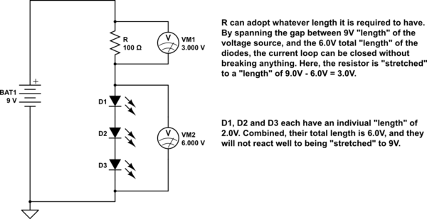
simulate this circuit – Schematic created using CircuitLab
In this analogy, current is the "force" with which you have to stretch the elastic. They stiffer the elastic, the more force is require to span the gap, the more current flows. Stiffer elastic corresponds to lower electrical resistance.
I won't go into the details of how to calculate R, there are a million web pages to help you work that out. This answer is just to set you straight about why Ohm's law doesn't apply to the diodes, and why the resistor (or some other means of "compliance") is necessary.
As with all semiconductor devices, intuitive understanding of diode circuits requires not only knowledge of semiconductor theory but also a functional understanding. We need to be able to imagine what these devices are doing in circuits to understand them.
The diode IV curve gives us the best idea of this. We can obtain it in two ways - by varying the current and measuring the voltage (V = f(I)), or by varying the voltage and measuring the current (I = f(V)). The first way is preferable because it allows obtaining more points; the second is generally accepted and can be easily implemented by the CircuitLab DC sweep simulation if we set the simulation step small enough.
I have shown the evolution of the diode representation by separate "shots" of the setup that correspond to some (operating) point from the IV curve.
So the measuring setup is simple - a voltage source connected through an ammeter to the diode. The only thing that is required of us is to carefully change the voltage within the permissible limits (somewhere up to 0.8 V for an Si diode) so as not to exceed the maximum permissible current of the diode (for example, 100 mA).
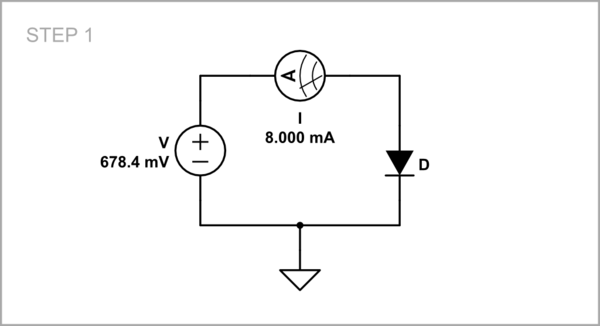
simulate this circuit – Schematic created using CircuitLab
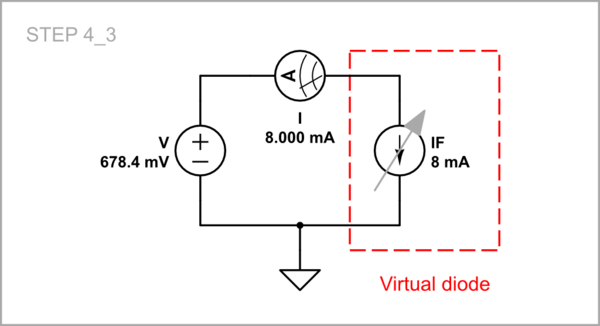
As you can see, to represent the point 2 from the graph below in the setup, I have adjusted the voltage to 678.4 mV to cause 8 mA current flowing through the diode. In the DC sweep parameters, I have set a voltage range 0 ÷ 690 mV.
Looking at this highly non-linear curve, we want to somehow understand how the diode does it.
For the purposes of intuitive understanding and calculating, we can replace (model) the more sophisticated real diode by simpler and well-known equivalent electrical devices or circuits.
A rather crude textbook simplification is to represent the curve as assembled from two segments - horizontal and close to vertical. As they explained to me as a student in the 70's, the devices that represent them can be an "ideal" diode and a low resistance resistor in series. Back then I was unsuccessfully trying to buy an "ideal" diode from the electronics stores :-) but now I see that CircuitLab gives me the opportunity to use as many "ideal" diodes as I want for free. Let's then take one and set the values of its forward voltage (in parameters) and resistance R so that the circuit corresponds to point 2 in the graph above.
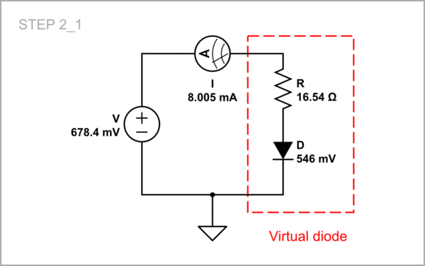
This is what the IV curve looks like for our simplified diode (that is how it looked in my student textbooks too).
But the "ideal" diode was something quite abstract, and maybe that is why others presented the diode to me as an "ideal" voltage source and a low resistance resistor in series. This brought me new frustrations at the time because I was unsuccessfully trying to power a small radio receiver with a few diodes in series:-) But let's try it now with the help of CircuitLab.
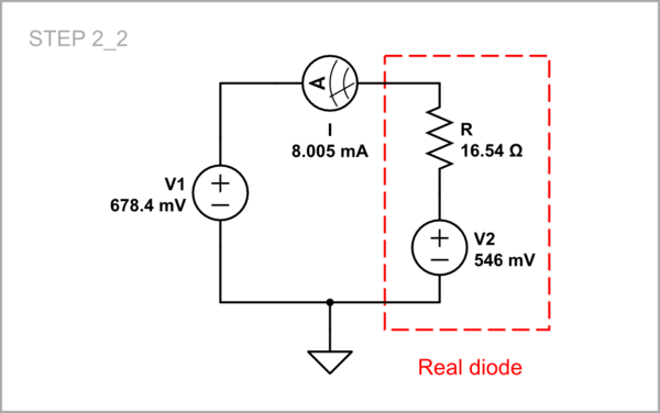
The IV curve should look like this…
... but here is what the graph is. Obviously, this is not a very good model for beginners...
As you can see, when V1 < V2, the "diode voltage source" can supply the input device:-)
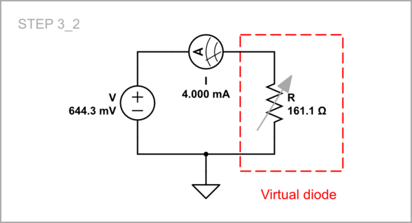
I understood what the diode actually did when I imagined it as a varying, "dynamic" resistor which varies its resistance so as to maintain a relatively constant voltage. Let's see what it is for three typical points on the curve.
Point 0: VF = 425 mV; IF = 0 mA, R = infinite.
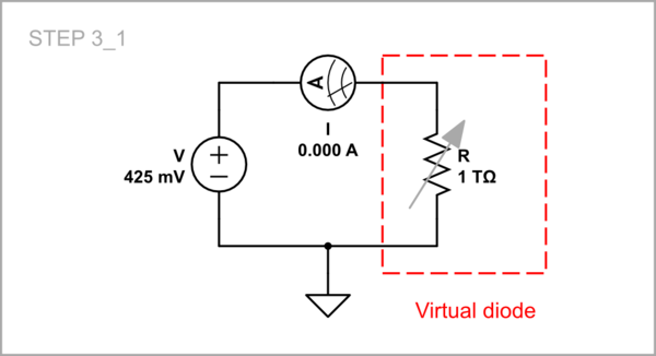
Point 1: VF = 644.3 mV, IF = 4 mA, R = 161.1 ohm.
Point 2: VF = 678.4 mV, IF = 8 mA, R = 84.8 ohm.
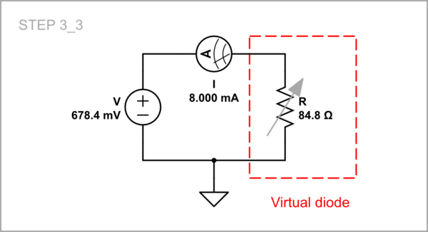
As we can see as the voltage increases the resistance decreases and the IV curve is almost vertical.
Thus, if you continuously adjust the resistance for each value of the input voltage, you will mimic the real diode. If you hide in a box together with the resistor, the outside observer will think that there is a diode inside :-)
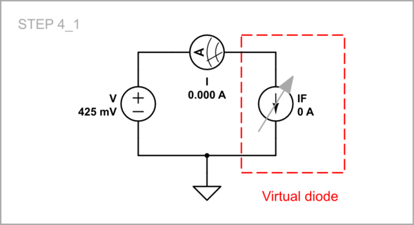
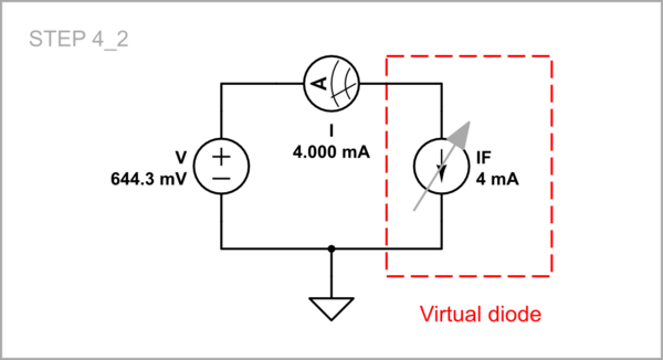
We can even make (model) a diode by a "dynamic" current source changing its current in the same way when the voltage varies. Here are the arrangements for the three typical points on the curve.
Point 0: VF = 425 mV; IF = 0 mA.
Point 1: VF = 644.3 mV, IF = 4 mA.
Point 2: VF = 678.4 mV, IF = 8 mA.
This idea is implemented in the so-called "active diode". As an example, let's make the schematic above this way.
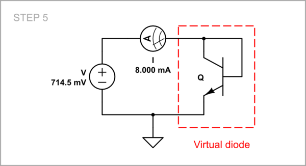
Here the transistor is a current "source" that adjusts its collector current so that to keep the respective voltage across itself.
See also my answer 1 and 2.