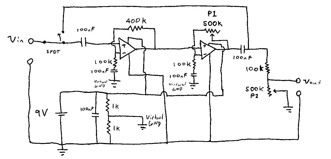
I have attached an image of an overdrive circuit that I have designed for a guitar pedal. I have built the circuit and it isn’t working and I wanted to find out if there were any obvious design flaws/things I need to change or consider? I’m new to signal processing.
The first potentiometer is meant to control the gain of the signal and introduce clipping whereas the second potentiometer is intended to control volume of the output signal.
I have made the assumption that the input signal is approx 200mV pk so the first op amp increase the signal amplitude to approx. 1V pk; the second op amp is then intended to further increase the amplitude until it is driven beyond the rail supplies which will clip the signal at 4.5V pk (achieved through a voltage divider).
-
\$\begingroup\$ Looks like your virtual ground (weak as it may be) is hooked to the negative end of your 9 V supply. This effectively shorts out (bypasses) one of the resistors in your divider. What's up with that? \$\endgroup\$– periblepsisCommented Sep 29, 2023 at 0:32
-
\$\begingroup\$ Besides what mentioned above the schematic is fine, though you should put a resistor in series with P1 to limit it's value.. And, P2 is kind of weird, if you are using a 3-pole potentiometer you should use the center tap as the output and connect other two contacts to ground and signal. And, finally, don't just put a capacitor in the positive opamp terminal path (see your first capacitor), use an RC circuit to VG. \$\endgroup\$– sx107Commented Sep 29, 2023 at 0:35
1 Answer
I have built the circuit and it isn’t working
What does that mean? Is it totally dead, is it amplifying but not clipping, is it picking up old Star Trek reruns?
To start with, the virtual ground must be decoupled at all audio frequencies of interest. As it is, it looks like a 500 ohm resistor to GND and all signals connected to it interact. As a starting point, use a 100 uF electrolytic and 0.1 uF to 1.0 uF ceramic in parallel.
Also, add a 0.1 uF ceramic capacitor at each opamp's power pins. Place it (them) close to the device pins, and the leads as short as possible.
There is no DC path to GND for the first opamp. The non-inverting input must have a DC voltage to establish an operating point for the input stage. A 0.33 uF cap to GND will form an input highpass filter with a corner frequency of around 5 Hz.
Due to the feedback components used, each stage is acting as a highpass filter with a corner frequency of 16 Hz. The two stages combine such that the frequency response at 16 Hz is down 6dB from "flat", and down 3 dB at 32 Hz. We don't know what your bandwidth requirements are, so this may or may not be an issue.
Also, please add unique reference designators to each component, pin numbers on the opamps, and repost. Without this, discussing the performance of individual components is . . . difficult.
-
1\$\begingroup\$
There is no DC path to GND for the first opamp.that's almost certainly the answer, with no DC path input bias current will rail the op-amp's input. \$\endgroup\$ Commented Sep 29, 2023 at 3:21 -
\$\begingroup\$ @Jasen Yup. That's a(nother) problem with the circuit. \$\endgroup\$ Commented Sep 29, 2023 at 4:54
-
\$\begingroup\$ That's the third point I listed. Did you mean to comment on the first post, not my response? \$\endgroup\$ Commented Sep 29, 2023 at 14:47
