1
\$\begingroup\$

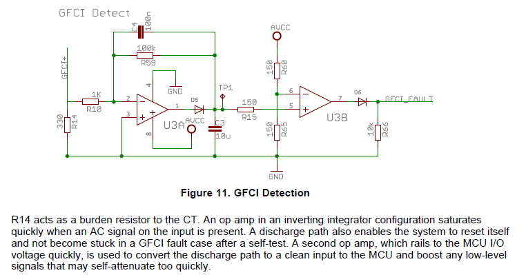
enter image description here

Above is a snippet taken from a TI app note from here.

It a GFCI circuit. There are saying to connect a CT. Can someone tell me the working in a little more detail and the flow of current and voltage in the circuit?

Why are the resistors R15, R60, R65 so low in value and R59 , R66 high in value?

Also, to what should I connect the GFCI+ net in the above diagram?

\$\endgroup\$
2
  • 1
    \$\begingroup\$ Edit your topic to really be a topic. Right now it doesn't say anything about your question. Also, where in the link is this note? \$\endgroup\$
    – MiNiMe
    Commented Oct 11, 2023 at 12:29
  • \$\begingroup\$ Freshman - Hi, (a) As commented, where on the webpage you linked is the PDF with that image you copied? I couldn't find it after a quick search there. (b) The above question is related to this question you asked in June, where you gave a different link to the document, but it is now a 404 on TI's website :( I recommend that you link to the earlier question in today's new question, to avoid people wasting time repeating the same answer that you got there, about how that part works. Thanks. \$\endgroup\$
    – SamGibson
    Commented Oct 11, 2023 at 13:31

1 Answer 1

0
\$\begingroup\$

GFCI+ is the difference signal in the event of a short circuit. Assuming that the maximum value of the sinusoidal voltage, at the input to the system, indicated with GFCI+, is 125mV and given that the U3A has a negative feedback, during the negative half-wave of the input, the output voltage of U3A is positive. Initially, considering C3 at zero voltage, the diode is in conduction and can be considered as a closed switch, meaning that the operational amplifier, in the half-period, is in the configuration of an inverting integrator, so in this half-period, the output of the OpAmp U3A is proportional to the integral of the input signal. This happens in the interval T/2-T where T is the period of the input signal. For t=T, the input half-wave inverts becoming positive, and the output of the OpAmp U3A is negative so as to reversely bias the diode D5 while C3 has charged to the value vo(T) discharging through R15 and the input resistance of the second OpAmp U3B. In the following half-cycle of the input signal, the diode D5 will start conduction as soon as the voltage across its terminals is positive, this voltage is given by the difference between the voltage at the output of the operational U3A and the voltage across C3. The voltage across C3 is placed at the non-inverting input of the second OpAmp U3B, which is in comparator configuration, i.e. it compares the non-inverting input voltage with the voltage Vcc/2 at its inverting input. As soon as this voltage is higher than Vcc/2 the comparator switches and goes into saturation. As soon as the input voltage of U3B becomes less than Vcc/2, the output of U3B switches to zero. ultimately at the output of U3B, on load R66 after D6, there is a train of PWM pulses.

\$\endgroup\$
10
  • \$\begingroup\$ Thank you for your answer. Can you please explain a little more when you say, "GFCI+ is the difference signal in the event of a short circuit.". I assume the GFCI+ is an input. But can you please explain where it is a sinusoidal signal and where should the current transformer (CT) be connected in the circuit? \$\endgroup\$
    – Freshman
    Commented Oct 11, 2023 at 17:41
  • \$\begingroup\$ Also, can you tell me why such a circuit is required? What is the purpose of the Integrator configuration in the U3A op-amp? Also, why should this circuit have PWM as output? If so, would the PWM frequency be the same as the input frequency? Why D6 is required? \$\endgroup\$
    – Freshman
    Commented Oct 11, 2023 at 17:57
  • 1
    \$\begingroup\$ In the event of current leakage in the two-wire electrical system, a difference is created in the current intensity between the two wires. This current circulates in a coil which generates a differential voltage. This voltage must be placed between GFCI+ and ground. Search GFCI online, you will find many answers. \$\endgroup\$ Commented Oct 11, 2023 at 17:58
  • \$\begingroup\$ Also, if the op-amp is required to be in integrator configuration, why should there be 100k is parallel across the C4? What purpose does the C4 serve? \$\endgroup\$
    – Freshman
    Commented Oct 11, 2023 at 17:58
  • \$\begingroup\$ Thank you for your comment. Could you also tell me the purpose of R14 and why is it so low in value? Can it be of higher value? \$\endgroup\$
    – Freshman
    Commented Oct 11, 2023 at 18:00

Your Answer

By clicking “Post Your Answer”, you agree to our terms of service and acknowledge you have read our privacy policy.

Not the answer you're looking for? Browse other questions tagged or ask your own question.