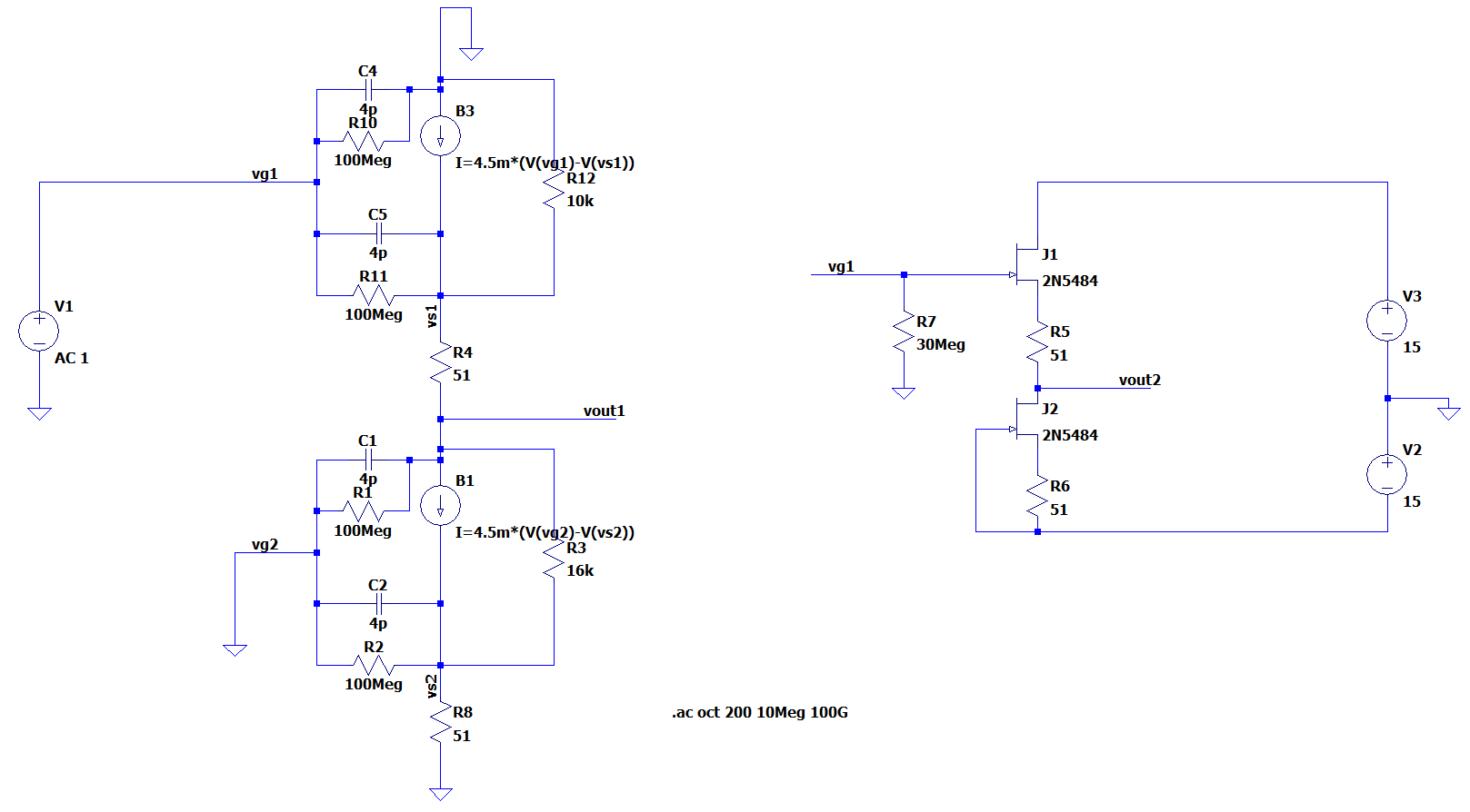
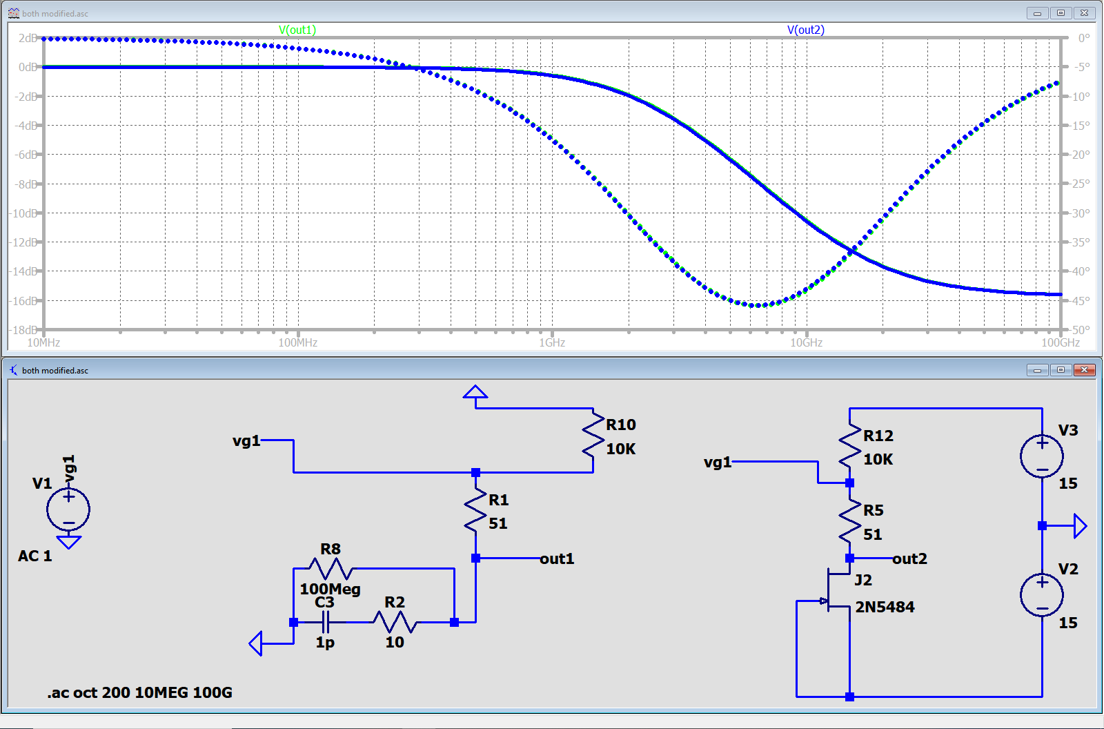
I was solving for poles and zeros of this JFET amplifier with an active load, and found an unexpected zero far off in the response when using the SPICE model. The large-signal and small-signal models are shown below.
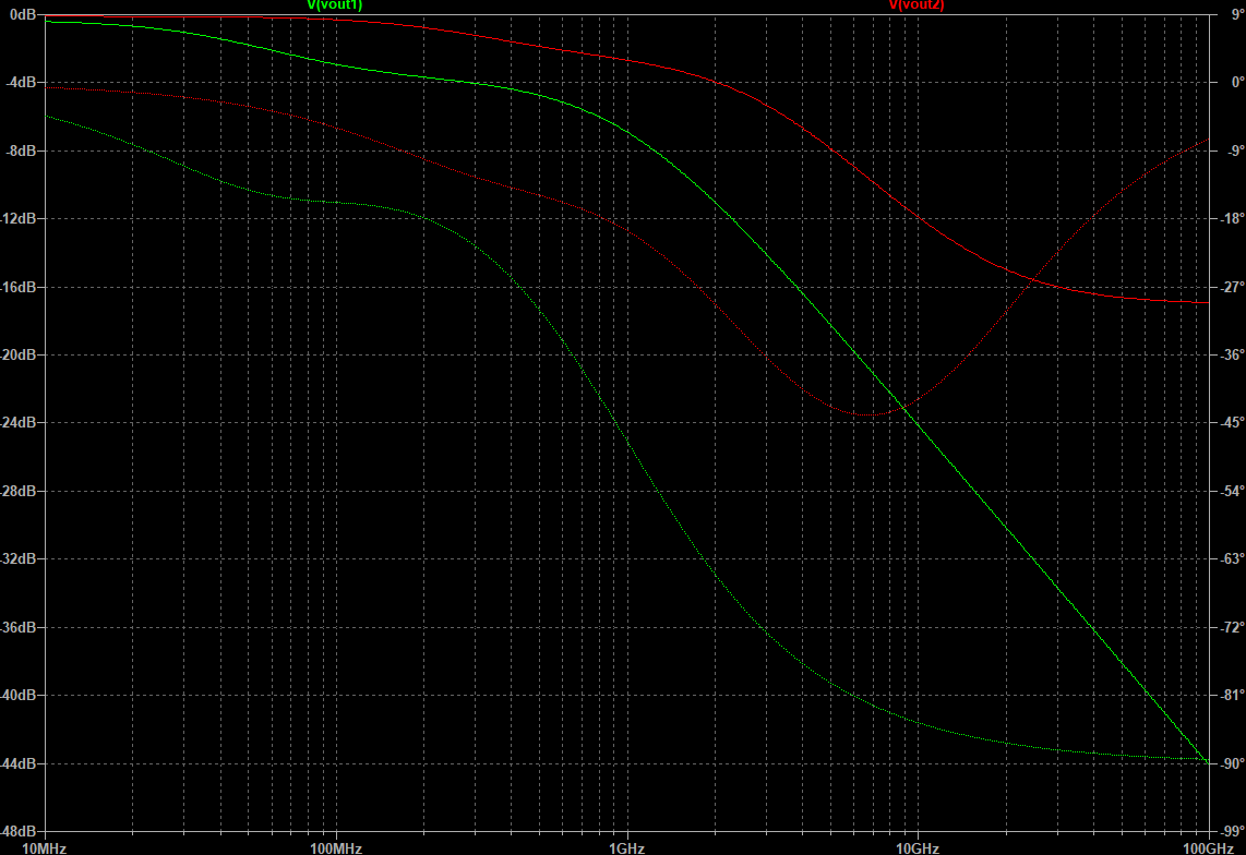
The device parameters (Cgs, Cgd, gm) are more or less approximate, but still, the simulated transfer functions are very different around the break frequencies (green=small-signal model, red=SPICE JFET):
According to the SPICE 3 User's Manual (among other references), level 1 JFET models use the Shichman-Hodges model for FETs, and this model only includes two capacitances, though a third capacitance (Cds) can be included. I've never seen a JFET small-signal model that had other capacitances (probably because in practice for high frequencies the lumped element thing breaks down anyway and we use $y$-parameters).
The thing is, the transfer function for the SPICE version has a zero around 21 GHz, whereas the small-signal model falls off after the (more or less) dominant pole around 1.125 GHz.
The disagreement between these two models is significant, even in the 10MHz - 500MHz region, although adjusting the JFET models can help somewhat by pushing the cutoff around.
But why is there such strong disagreement beyond 1 GHz for these two models? What model does SPICE (or only LTSpice) use that results in the extra zero in the response?

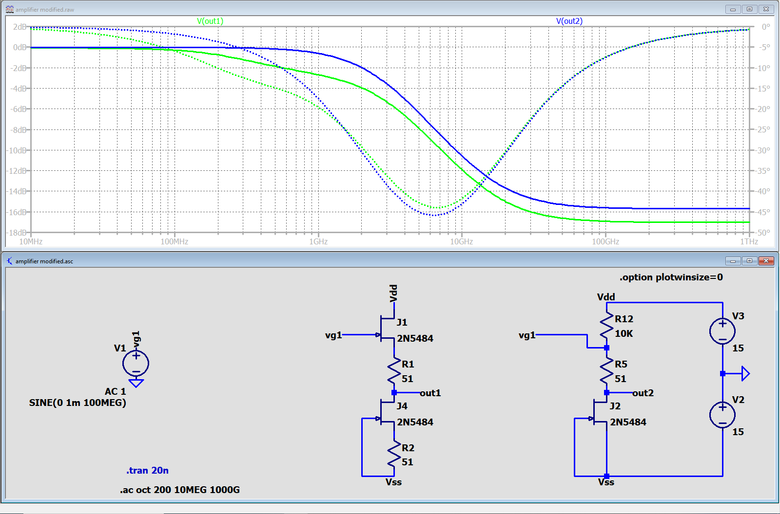
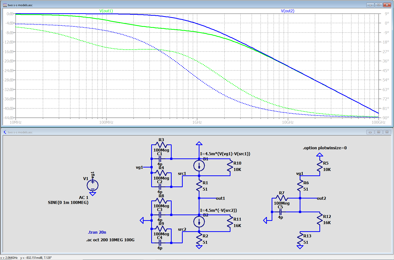
.op, then run it and close the report window. Then open the SPICE Error Log (CTRL+L) to see what LTspice internally calculates for the small signal parameters for J1 & J2. Then compare those to your calculations. \$\endgroup\$