0
\$\begingroup\$

Can we use tunnel diodes to cancel out armature resistance?

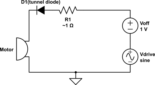
A tunnel diode when it is in its negative differential region under DC shifted AC(AC with some DC offset) and if the Vp-p of the AC is very small behaves like a resistor with negative resistance.

Usually the absolute value of this negative resistance is really small ~ 1Ω so we cant use it to cancel out the resistance of lets say a lamp BUT the armature resistance of a AC motor is in the range of 1Ω so in that way:

schematic

simulate this circuit – Schematic created using CircuitLab

Since \$I\$ would become very big , the motor would rotate very very fast so I suspect it would reach saturation.Am I correct?

\$\endgroup\$
9
  • \$\begingroup\$ The tunnel diode has a negative incremental resistance, you can't use it to cancel copper resistance and create a superconductor. (If that's the question, it's not 100% clear to me.) \$\endgroup\$
    – John D
    Commented Nov 20, 2023 at 21:39
  • \$\begingroup\$ Yes in DC.Under AC its differential resistance is negative.The resistance in DC \$\ne\$ the resistance in AC. \$\endgroup\$
    – user355819
    Commented Nov 20, 2023 at 21:39
  • \$\begingroup\$ Think of a tunnel diode as an "overacting dynamic resistor". When the voltage across it increases, it increases (but to a greater extent) its resistance, and v.v. In this way, it modulates the current in the circuit and, accordingly, the voltage drop created across the load. This is what we call "amplification". So the tunnel diode acts as the transistor but it is a 2-terminal device connected in series to the input voltage source, power supply and the load. \$\endgroup\$ Commented Nov 20, 2023 at 21:53
  • \$\begingroup\$ @Circuitfantasist but I can prove out that a tunnel diodes has in some range AC negative resistance I will load it up. \$\endgroup\$
    – user355819
    Commented Nov 20, 2023 at 22:09
  • \$\begingroup\$ I think you might be confusing "AC resistance" with reactance and are inventing a capacitor. \$\endgroup\$
    – vir
    Commented Nov 20, 2023 at 22:20

2 Answers 2

2
\$\begingroup\$

Revealing the secret of negative differential resistance by CircuitLab experiments

Experimental setup

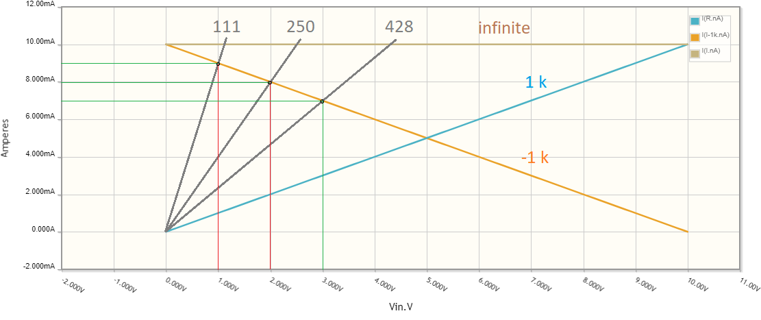
According to my comments above, two resistors are connected in parallel - R1k with a 1 kΩ "positive" resistance, and R-1k with a 1 kΩ "negative" resistance. I have put both names in square quotes because these resistances are neither negative nor positive, but the most common ohmic resistance known since the 19th century. So the negative differential resistance of -1 kΩ is implemented by a variable resistor whose resistance changes from 111 Ω to infinity when Vin varies from 1 V to 10 V.
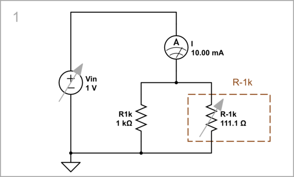
schematic

simulate this circuit – Schematic created using CircuitLab

We need to observe the currents flowing through the resistors. To simplify the schematics, we can combine the resistors with the ammeters into one device ("visualized resistor"). To do this, open the parameters window of each of the two ammeters and set the corresponding internal resistance.

Step-by-step experiments

To understand the mechanism of this so-called "N-shaped negative differential resistance", let's first examine the circuit at three successive values ​​of the input voltage - 1, 2 and 3 V.

Vin = 1 V, R-1k = 100 Ω: At 1 V input voltage, the 1 k positive resistor consumes 1 mA. The negative resistor has a 111 Ω resistance, so 9 mA current flows through it, and the total current consumed is 10 mA.
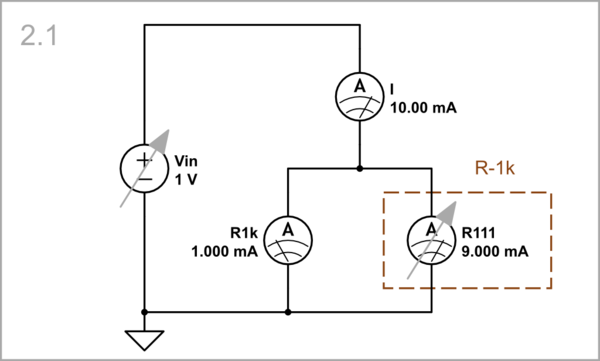
schematic

simulate this circuit

Vin = 2 V, R-1k = 222 Ω. When the input voltage increases to 2 V, the negative resistor increases its ohmic resistance to 250 Ω. Now the positive resistor consumes 2 mA but the negative 8 mA, and the total current consumed is again 10 mA (i.e., the left current increases but the right current decreases, and their sum I remains constant).
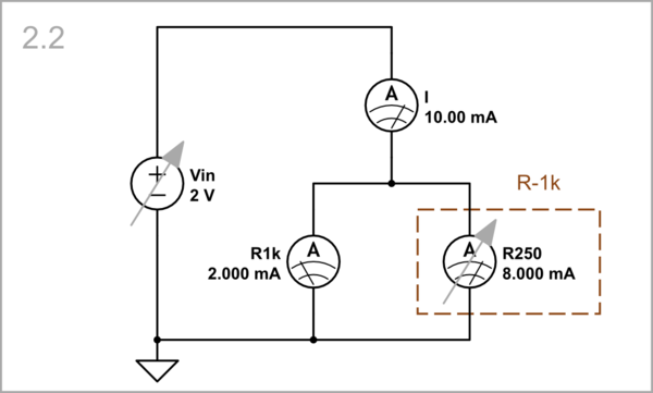
schematic

simulate this circuit

Vin = 3 V, R-1k = 375 Ω: Next, the input voltage increases to 3 V, and the negative resistor increases its ohmic resistance to 428 Ω. The positive resistor consumes 3 mA but the negative 7 mA, and the total current consumed is, as usual, 10 mA... and so on...
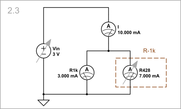
schematic

simulate this circuit

Automated experiment

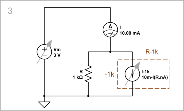
To sweep the negative resistance, we can simulate it using a behavioral current source I-1k that produces a current 10 mA - IR.
schematic

simulate this circuit

Graphical representation

From the graphs below, we see that as the input voltage increases, the current through the positive resistor increases and through the negative resistor decreases because its resistance increases. The result is a constant common current which is seen by the input voltage source as an infinite differential resistance.
STEP 3

Applications

I will illustrate my conceptual explanations above by solving a specific circuit problem - eliminating the impact of the load on the output voltage of a voltage divider.

Experimental setup

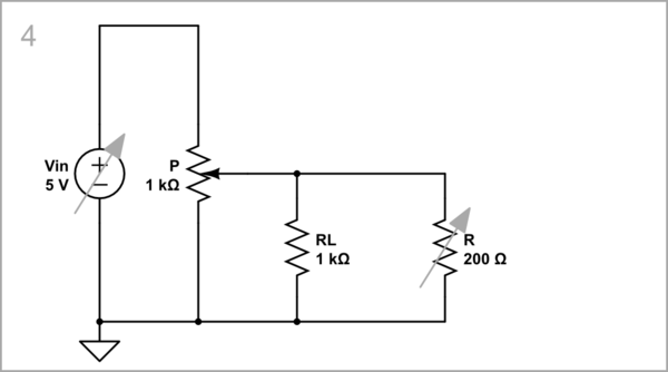
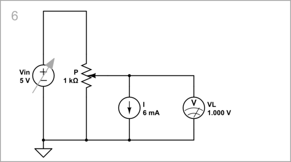
In the schematic below, a potentiometer P is loaded by a 1 kΩ "positive" resistor RL. A 1 kΩ (N-shaped) negative differential resistor R with initial resistance of 200 Ω is connected in parallel.
schematic

simulate this circuit

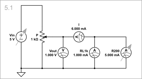
Vin = 5 V, R = 200 Ω: As a result, a total current I = 6 mA is consimed from the potentiometer output, and its output voltage is 1 V. Note that to simplify the schematic, I have implemented the resistors with "bad" ammeters having the same internal resistance (RL1k = 1 kΩ, R = 200 Ω).
schematic

simulate this circuit

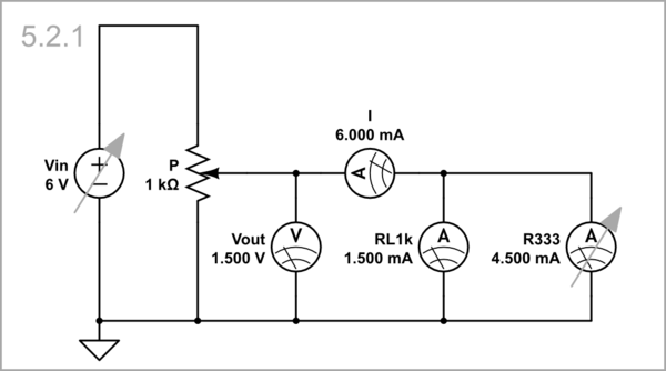
Vin = 6 V, R = 333 Ω: When we increase Vin with 1 V, the potentiometer output voltage begins increasing. Simultaneously, the "negative" resistor R increases its resistance to 333 Ω thus compensating the influence of the positive load.
schematic

simulate this circuit

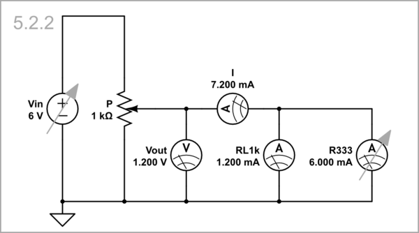
As a result, the output voltage becomes 1.5 V instead of 1.2 V as it would be if R had not increased:
schematic

simulate this circuit

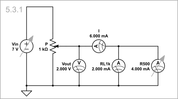
Vin = 7 V, R = 500 Ω: When we increase Vin by another 1 V, the potentiometer output voltage begins increasing even more. The "negative" resistor R increases its resistance to 500 Ω thus compensating the influence of the positive load.
schematic

simulate this circuit

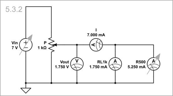
The output voltage becomes 2 V instead of 1.75 V as it would be if R had not increased:
schematic

simulate this circuit

Equivalent circuit

So, the voltage divider is loaded with a 6 mA constant current source I, and the output voltage variations are not influenced by this extremely high-resistance load.
schematic

simulate this circuit

Conclusions

  • The N-shaped negative differential resistor (e.g. a tunnel diode) is a dynamic resistor that increases its static (ohmic) resistance when the voltage across it increases.

  • If connected in parallel to an equivalent "positive" resistor, it neutralizes its resistance so that the equivalent resistance is infinite.

So this is not what OP need. They need:

  • a dynamic resistor that decreases its static (ohmic) resistance when the current through it increases.

  • It will be connected in series to an equivalent "positive" resistor so that to neutralize its resistance, and make the equivalent resistance zero.

See also another story of mine dedicated to this circuit phenomenon.
\$\endgroup\$
1
\$\begingroup\$

No you can't do that since it does not have absolute negative resistance.

We do use IR compensation in motor speed controls to negate armature resistance though. It's done with an electronic circuit, basically to measure the armature current and increase the voltage to compensate for the I*R drop- no weird components like Esaki diodes are required.

Ideally, it means the motor will maintain a constant speed proportional to applied voltage regardless of mechanical loading. Without such "IR compensation" the motor speed will drop as the load and therefore armature current increases.

\$\endgroup\$
5
  • \$\begingroup\$ Spehro Pefhany, Of course, the tunnel diode implementation is not practically feasible, but the question is more conceptual, and consists in whether the goal can be achieved with such an element (negative differential resistor). By itself, it is a passive element (in the sense that it does not "produce" power). But I think that in combination with a source it becomes an absolute negative resistor, and can compensate for a positive resistance. This idea is difficult to realize even with an op-amp circuit of a true negative resistor (VNIC) because the current through the motor is very high. \$\endgroup\$ Commented Nov 25, 2023 at 21:19
  • 1
    \$\begingroup\$ @Circuitfantasist I think if you start with a motor speed control where output voltage is proportional to input (either from a DC signal or a potentiometer) adding IR compensation does not require much additional complexity or difficulty. No additional high currents involved except maybe in measuring the armature current if a shunt resistor is used (rather than something like Hall effect). \$\endgroup\$ Commented Nov 25, 2023 at 21:29
  • \$\begingroup\$ Spehro Pefhany, the "IR compensation" is well known in negative feedback electronic circuits. For example, the popular op-amp circuit of a transimpedance amplifier is based on it. There an op-amp compensates for the IR drop across the feedback resistor R by adding a voltage of the same value in series and in the same direction with the input voltage. The result is zero voltage at the inverting input (virtual ground) and zero resistance between the inputs (virtual short). In this way, as though the R positive resistance is neutralized (zeroed) by the op-amp output "negative resistance". \$\endgroup\$ Commented Nov 25, 2023 at 21:36
  • 1
    \$\begingroup\$ Spehro Pefhany, I understand you... but I hope you understand me too. I am looking to derive and explain as general a principle (concept) as possible and not so specific a circuit solution. Otherwise, I have an idea of ​​the complexities in the theory and practice of this field... \$\endgroup\$ Commented Nov 25, 2023 at 21:44
  • 1
    \$\begingroup\$ @Circuitfantasist I think the answers are complementary. \$\endgroup\$ Commented Nov 25, 2023 at 21:48

Your Answer

By clicking “Post Your Answer”, you agree to our terms of service and acknowledge you have read our privacy policy.