0
\$\begingroup\$

Is there a circuit that can produce an asymmetric wave, where some parameters of positive and negative half waves are different, such as voltage amplitude or time?

Intuition says that we need a component that acts differently to the positive and negative voltage. A diode does that, but when I test it in a simulator it shows a symmetrical sine wave, so my intuition is wrong ,which means that I don't understand some important aspect of it. The naive view says something like 'in one half wave a x2 inductor is active, and in other half wave a x1 inductor is active.'

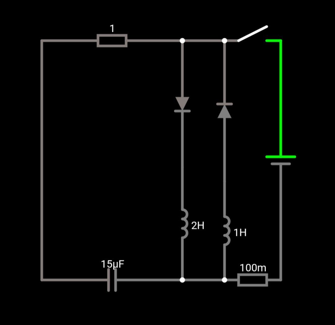
Circuit: battery, switch and LCR parallel circuit, where L is doubled and each has a diode facing antiparallel, and one of the L has twice the inductance:

LCR with diodes

The perfect answer would explain the difference between the naive view and the simulation result and if there are any similar circuits that consist of resistors, inductors (can be coupled), capacitors, diodes that can produce a wave with half waves of positive and negative voltage on a capacitor which are not the same in time or amplitude.

\$\endgroup\$
3
  • \$\begingroup\$ Instead of describing your circuit in text, please draw a schematic. Also, what’s vew? View? \$\endgroup\$
    – winny
    Commented Jan 10 at 13:42
  • \$\begingroup\$ @winny added the schematic, fixed typos \$\endgroup\$ Commented Jan 10 at 13:46
  • \$\begingroup\$ Try using two capacitors in series with opposing diodes. Diodes and series inductees won't work as you expect. It may still not work as you expect but, you should do the work to prove what happens. \$\endgroup\$
    – Andy aka
    Commented Jan 10 at 14:06

2 Answers 2

1
\$\begingroup\$

It's technically possible.

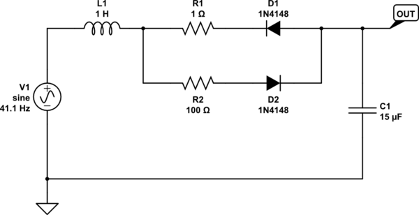
For the circuit below, for example, the main idea is to change the damping whilst maintaining the tank resonance frequency:

schematic

simulate this circuit – Schematic created using CircuitLab

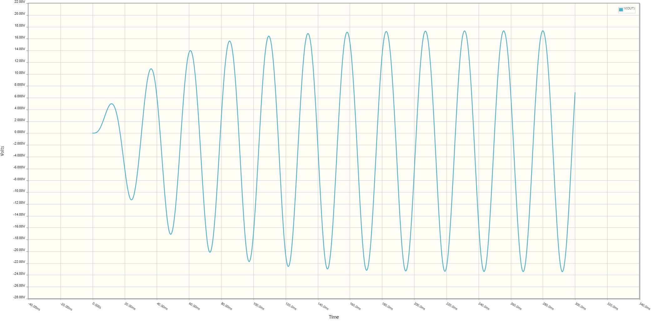
You can simulate the circuit above with different R1 and R2 values for different amplitudes. Below is the simulation result for the given values:

enter image description here

So the positive peak hits ~18V and the negative one hits ~23V.


From your comment under Stefan Wyss's answer:

But is there a similar way that dissipates less energy? Without the loss on the resistor being the main source of asymmetry of the waveform

In case you ask the same question, I'm going to answer here:

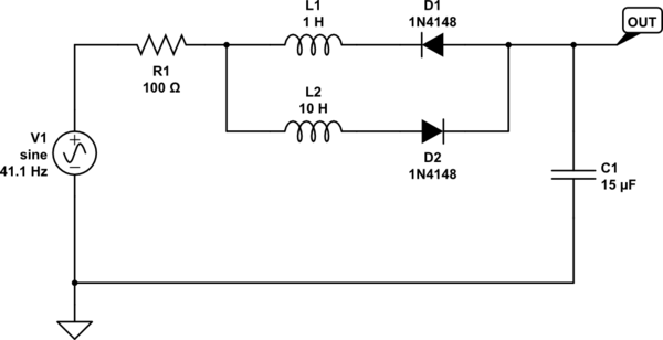
Yes, it's possible. In the circuit above, if you replace R1 and R2 with inductors, and L1 with a resistor, you can still have a similar behaviour. However, to create a substantial amplitude difference, the inductance ratios should be high accordingly. Here's an example:

schematic

simulate this circuit

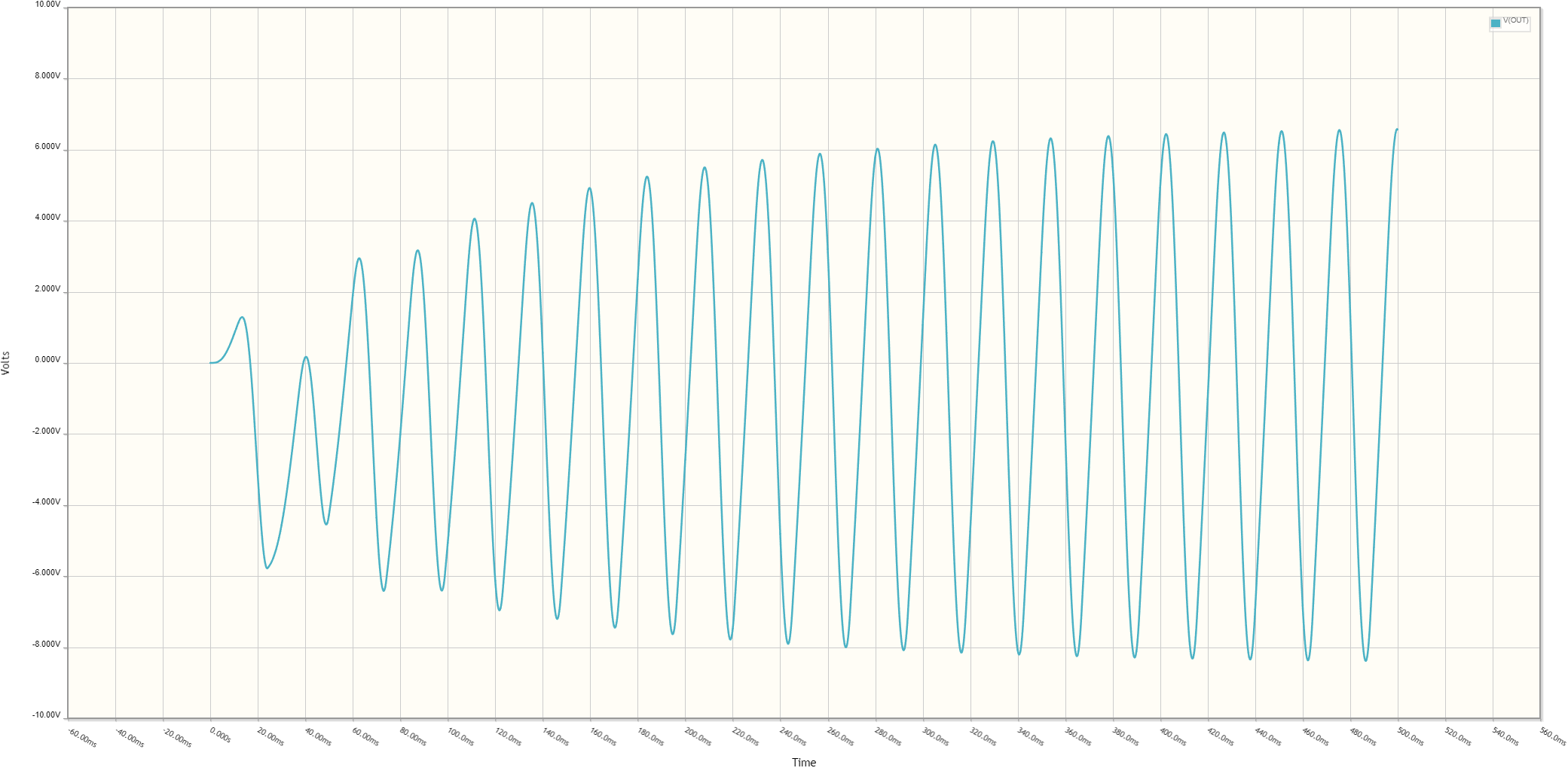
Just like the other one, you can simulate this circuit. Here is a simulation result for the values above:

enter image description here

The positive peak passes 6V and the negative one passes -8V.

\$\endgroup\$
3
  • \$\begingroup\$ It is the most complete solution, but it still burns most of the energy it gets. I was hoping there is a solution that is efficient, where quality factor 100 is possible, and that has a significant waveform asymmetry. In this case quality factor is closer to 1. \$\endgroup\$ Commented Jan 10 at 21:59
  • \$\begingroup\$ @SurprisedSeagull to get practically high Q factor the resistive component should be as low as possible. In the circuit above the resistor can be 1 Ohms, inductors can be 10H and 100H, and the capacitor can be 1.5 uF. In this case, the I²R loss will be less (neglecting the inductors' DCR) but the amplitude difference will be less as well. I just simulated a circuit with a R1 of 1 Ohm, L1 and L2 of 10 and 100 Henries, and C1 of 150n. The circuit settles after ~2 seconds and the amplitude difference is only 3 Volts. By the way, without a resistor, you may experience waveform discontinuities. \$\endgroup\$ Commented Jan 11 at 7:23
  • \$\begingroup\$ this whole family of solutions trades efficiency loss for asymmetry. The more there is an efficiency loss in the resistor, the greater the asymmetry. The quality factor of 100 and the asymmetry of 1.1 at the same time cant be achieved with this family of solutions. Ideally I want both, the efficiency and the high asymmetry. \$\endgroup\$ Commented Jan 11 at 14:55
1
\$\begingroup\$

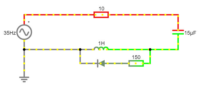
Of course you can influence the LC tank operation in a lot of ways. Here is an example of an asymmetric oscillating LC tank...

enter image description here

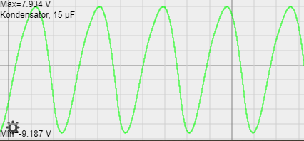
... with its waveform ...

enter image description here

\$\endgroup\$
3
  • \$\begingroup\$ That technically answers the question, so I will accept it. But is there a similar way that dissipates less energy? Without the loss on the resistor being the main source of asymmetry of the waveform \$\endgroup\$ Commented Jan 10 at 17:56
  • \$\begingroup\$ You could build very complex circuits with only L‘s and C‘s, but you need at least one diode for the non-linear part of the system response. Would you also accept active components like OpAmps? \$\endgroup\$ Commented Jan 10 at 20:02
  • \$\begingroup\$ idea is to use inductors, capacitors and diodes, as they can be considered close to ideal and cheap. Opamps have a lot of limitations. I understand that I can make any signal with OpAmps, but then im limited in frequency, voltage, current, efficiency, cost, temperature and many more. If there is no solution without OpAmps, then so be it, I wont follow this path. \$\endgroup\$ Commented Jan 10 at 21:56

Your Answer

By clicking “Post Your Answer”, you agree to our terms of service and acknowledge you have read our privacy policy.

Not the answer you're looking for? Browse other questions tagged or ask your own question.