1
\$\begingroup\$

Question:

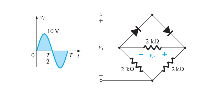
Determine the output waveform for the network(assume that all diodes are ideal)

enter image description here

The book says for the positive half-cycle it will be like this: positive half-cycle
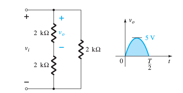
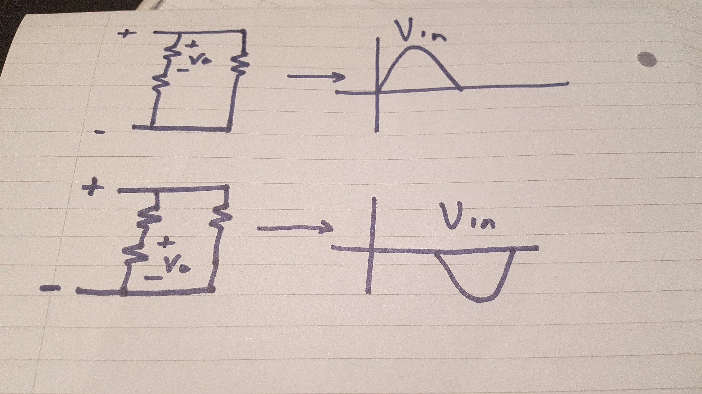
Similarly I think that for the negative half cycle it will be exactly like this except that the polarity of input voltages are flipped . But book says that the output waveform for the negative half-cycle will be same as positive half-cycle (in the positive region) .


But my intuition tells me that if the polarirites are flipped the output voltage must be in the negative region as current is entering from negative side of V0 .Am I missing something here ?

[I'm not allowed to post more than 2 image links]

\$\endgroup\$

2 Answers 2

2
\$\begingroup\$

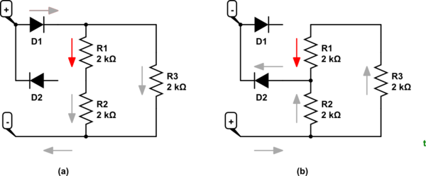
schematic

simulate this circuit – Schematic created using CircuitLab

Figure 1 (a) Positive half-cycle and (b) negative half cycle. Current is always the same direction in R1.

Disconnecting or removing components that are not relevant can often help in circuit analysis.

\$\endgroup\$
0
\$\begingroup\$

Your intuition is wrong here. The key point to achieving the same waveform at \$V_{o}\$ is to ensure current enters the same side of \$R_{vo}\$ regardless of \$V_{in}\$'s polarity, and this is the case here.

When \$V_{in}\$ is positive, \$R_{vo}\$ is simply the top resistor of the potential divider network.

When \$V_{in}\$ is negative, \$R_{vo}\$ is simply the bottom resistor of the potential divider network.

In both cases, current always enters through the right node of \$R_{vo}\$, hence ensuring \$V_{o}\$ is always positive.

enter image description here

\$\endgroup\$

Your Answer

By clicking “Post Your Answer”, you agree to our terms of service and acknowledge you have read our privacy policy.

Not the answer you're looking for? Browse other questions tagged or ask your own question.