4
\$\begingroup\$

This was a question asked to us by our client.The question is

'We have a TVS diode with a break down voltage of 31V.When a pulse of amplitude 31.7V and a duration of 100ms second is applied the diode will go break down.What will be the current flowing through this diode at this time'

May I know your thoughts about this.

\$\endgroup\$
2
  • 5
    \$\begingroup\$ You can't really know with just that info. TVS diodes with the same breakdown voltage but different sizes will have different impedances (and thus different voltage drops) when conducting different amounts of current. More current = higher voltage across the TVS. The amount of current conducted also depends on the source since the TVS loads it down. So the current is determined by equilibrium between loaded down voltage of the source and the TVS impedance. \$\endgroup\$
    – DKNguyen
    Commented Mar 12 at 16:30
  • 2
    \$\begingroup\$ If you don't know then you have to measure. It'd probably be quicker to measure than to write up this question if you are at the bench :) \$\endgroup\$ Commented Mar 12 at 19:26

3 Answers 3

8
\$\begingroup\$

May I know your thoughts about this

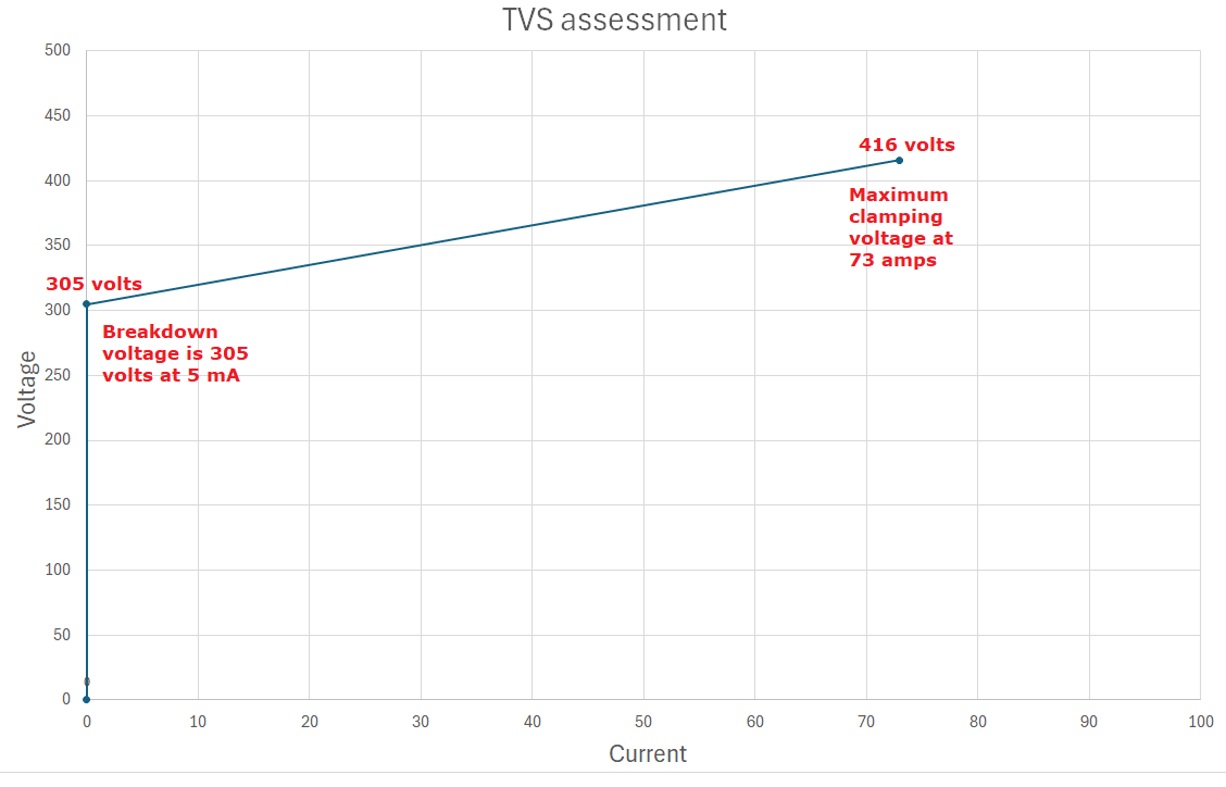
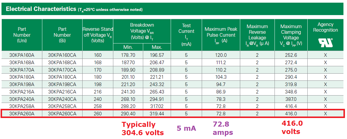
If I want to understand the current drawn by a TVS diode for a particular over voltage situation, I look at the data sheet. This is an exercise I recently did for the Littelfuse 30KPA260A: -

enter image description here

In simple terms you can plot the graph between the two points: -

enter image description here

Then you can easily see what current you might get for such and such an over-voltage.

But, be aware that a duration of 100 ms for a TVS is a very, very long time and, with the applied voltage (and subsequent current that flows), it could all end in a big cloud of magic smoke.

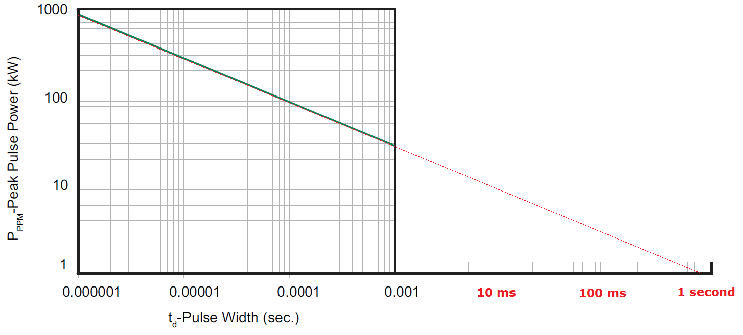
For instance, using the TVS above, the maximum power for about 1 second is this: -

enter image description here

I've extended the power graph to accommodate a 1 second pulse and, as you can see (for any part in the family), the continuous power will be slightly less than 1 kW for this duration.

Advice: be very careful about giving overly optimistic information to your customer so, look at the data sheet to ensure you understand the limitations of your device AND, be sure you understand the power supply specifications that the customer refers to.

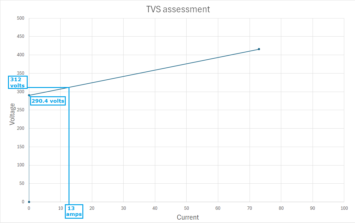
Device variations: For the device I used, if the typical breakdown is 305 volts, the actual rating for any part in a batch may be much lower i.e. 290.40 volts (as per information in the data sheet extract). This will make a big difference to the power dissipation. If I redrew my spreadsheet and marked on the slight amount of over-voltage (\$\frac{31.7}{31.0}\$) as you imply in the question, things look bad for the device: -

enter image description here

The current will be 13 amps at a voltage of 312 volts i.e. a power of 4.06 kW and this would destroy my device for a 100 ms pulse but, it might survive a 20 ms pulse.

However, if my device was exactly in the middle of the range of breakdown voltages (305 volts), about 7 amps would flow (during the over-voltage) and the power would be 2.184 kW. My device could survive this for about 200 ms.

There are very small margins on TVS diodes and, predicting whether a device will survive even a small over-voltage requires proper analysis and reliable details of the power source surge.

\$\endgroup\$
5
\$\begingroup\$

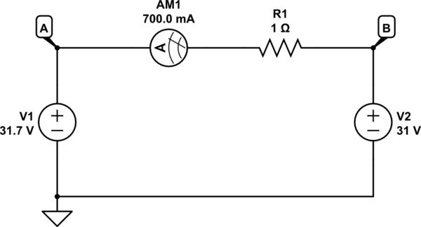
You can picture that scenario as a 31.7V source in parallel with a 31.0V source, and with some extra resistance in the loop:

schematic

simulate this circuit – Schematic created using CircuitLab

Think of this as a source V1 which absolutely refuses to allow any potential other than +31.7V at node A, and another element (the TVS diode, V2) that absolutely refuses to allow any potential above 31.0V at node B.

Clearly, without resistance R1 in the loop, that would be an impossible situation. In practice, though, the resistance R1 will be present, and it represents the combined resistances of all elements in the loop, including the two sources, and all the wiring.

In the above simulation, R1 is set explicitly to be 1Ω, and using KVL we can easily determine that it has 0.7V across it, resulting in a current calculable with Ohm's law:

$$ I = \frac{V}{R} = \frac{0.7V}{1\Omega} = 0.7A $$

However, it's unlikely that we can know to any precision what the real-life value of R1 actually is. All we can say, in practice, is that it's very low, and the resulting current will be very high.

You would need to know the internal resistances of all the elements present, including the 31.7V source, the TVS diode itself, and the wiring in this loop, to be able to predict the exact current that would flow.

To make things worse, the resistance of all these elements changes with current and temperature, and with current flowing, temperature rises with every millisecond that passes, so we have a real algebraic challenge on our hands.

\$\endgroup\$
3
  • \$\begingroup\$ This is very informative.May I know will I get the value of R1 from datasheet. \$\endgroup\$
    – Confused
    Commented Mar 12 at 17:15
  • 1
    \$\begingroup\$ @Hari If the datasheet is comprehensive enough to contain data from which you can infer its effective resistance, at some given temperature, and current, then yes. The problem is compounded, though, by resistances and rising temperatures everywhere, even the source of 31.7V itself. \$\endgroup\$ Commented Mar 12 at 17:20
  • 1
    \$\begingroup\$ @Hari Your response to your client should be: it's impossible to even estimate, without knowing a lot more about everything else in the circuit too. \$\endgroup\$ Commented Mar 12 at 17:23
3
\$\begingroup\$

An unusually (for me) hand-wavy answer, but may be helpful supporting information, while stopping short of a more strict-engineering-practices answer.

Common type TVSs are simply avalanche (zener) diodes, of unusual size (compared to signal types), and rated for peak power handling.

Therefore, everything that is true of zener diodes, is true of these as well.

First, note the breakdown range. Take SMAJ28A for instance: 31.1V min breakdown, 34.4 max, at 1mA. A random part may fall anywhere in this range, at this current. We are guaranteed that, if we operate precisely at 31.1V, at room temperature or above, no more than 1mA will flow.

We are recommended to operate (nominal continuous) up to only 28V of course, for which leakage current will be a nice reasonable 1µA (at room temperature). This also helps in that, real power sources have some tolerance on them, and we have a good 10% or so comfort range.

Avalanche varies with temperature. Looking up ye olde Motorola databook (p. 6-4-11 (324)) indicates about 2.5V range expected for a 30V diode from 25 to 125°C. Maybe call it 3V up to 150°C.

Finally, current increases exponentially with voltage above breakdown; expect around a decade increase every 60mV. If we have 1mA at 31.1V, 10mA at 31.16V or 100mA at 31.22V would be reasonable to expect.

What will happen is, if we wait for things to come to thermal equilibrium, the device draws enough power to reach a certain temperature, then current levels off. Say it takes 1W to raise it to 125°C; once stabilized, it will run at, say, 33.6V 29.8mA. Peak current can be almost arbitrarily high, until it stabilizes; ultimately peak current is limited by V(I) curve, which is more or less exponential plus some internal resistance, though we really only see that resistance manifest at very high currents (compare to the surge rating, 45.4V max. at 8.8A; we're surely not going to be drawing 8A at 31.7V, unless maybe at very low temperature).

Under transient conditions, you'll be somewhere along the transient thermal impedance curve. Unless it's a big diode (>3kW?), 100ms is probably on the order of quasi-thermal equilibrium, so the temperature and breakdown voltage will rise fairly quickly, and whatever the resulting current is, is what it will be.

Anyway, notice this isn't anything very hard and fast, because the breakdown voltage has a wider range. This is most relevant to min-spec parts, which -- if you don't mind the current draw or power dissipation, and don't have to worry about a power supply tolerance, this is the precise voltage you're applying -- you can indeed get away with applying voltage in the middle of the breakdown range, without component failure.

\$\endgroup\$

Your Answer

By clicking “Post Your Answer”, you agree to our terms of service and acknowledge you have read our privacy policy.

Not the answer you're looking for? Browse other questions tagged or ask your own question.