2
\$\begingroup\$

I used the LMR51430XFDDCR as a DC/DC power converter on my PCB. Upon connecting a fully charged 3-cell LiPo battery (12.5V), the converter instantly failed. The PCB is designed to draw no more than 2.5A, while the converter can supply up to 3A. Additionally, the IC is rated for a maximum input voltage of 40V, which is well above the 12.5V from the battery. I used TI's WEBENCH Power Designer to create the schematic and followed the layout guidelines provided in the datasheet. The PCB is made of 4 layers(upper layer: signal, in1: GND, in2: 3.3V and the forth layer, on the other side is also signal). Given these precautions, I don't know why the IC was damaged.

Reference Part
C24 CL10A475KO8NNNC
C26 GRM188R71H104KA93D
C30 GRM155R71C104KA88D
L3 744314650
R7 CRCW0402162KFKED
R8 CRCW040222K1FKED
C32 GRM32ER61C476KE15L

enter image description here

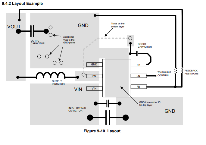
The TI's recommendation for the lmr51430XFDDCR:

enter image description here

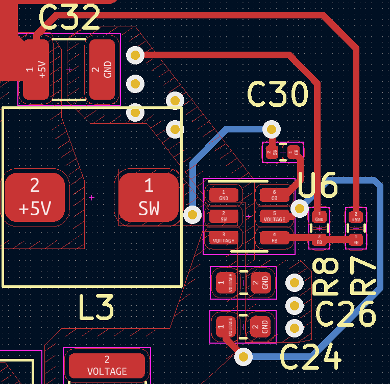
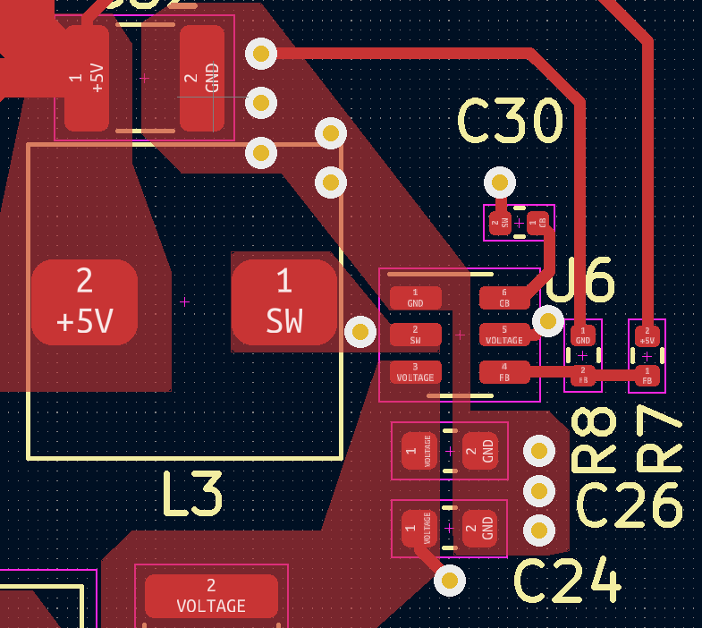
My layout:

enter image description here

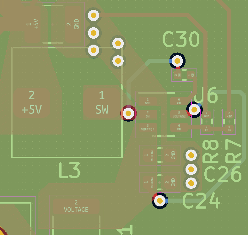
The GND pour:

enter image description here

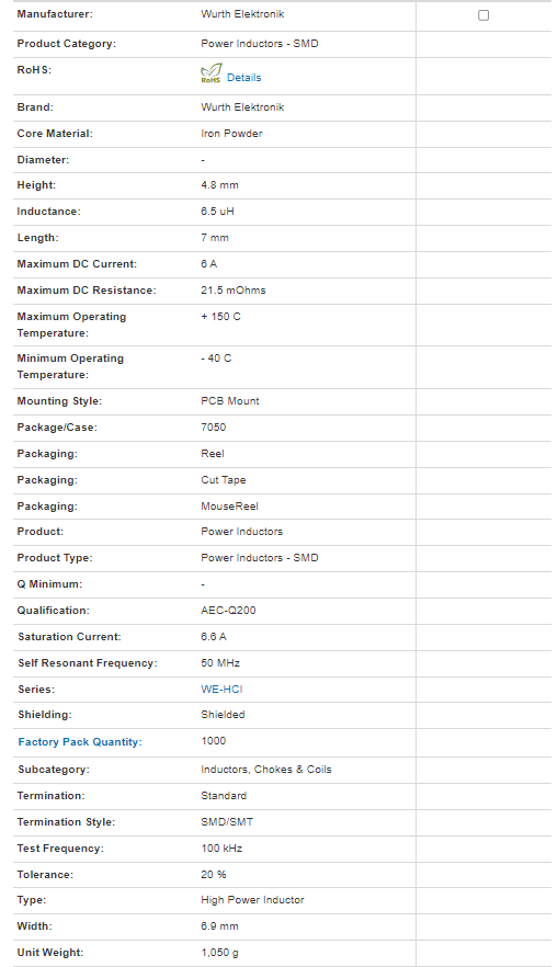
The inductor characteristics:

enter image description here

The copper pour on the top layer:

enter image description here

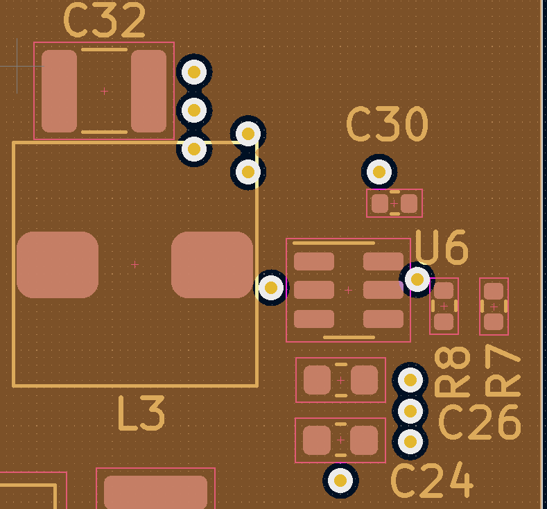
The GND plane(second layer):

enter image description here

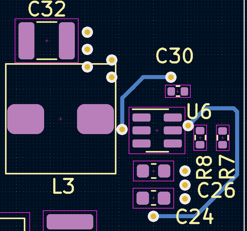
The 3.3V layer:

enter image description here

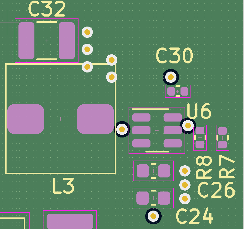
The signal layer on the bottom:
enter image description here

\$\endgroup\$
16
  • 1
    \$\begingroup\$ Is it possible the PCB has an inrush current that could cause the IC to fail on startup? \$\endgroup\$
    – InBedded16
    Commented Sep 24 at 14:33
  • 1
    \$\begingroup\$ @Robert interesting. Well you may want to pump those capacitors up to 25V ratings. Just because a capacitor is rated for 16V does not mean it is effective up to that voltage, the datasheet for C24 is a good example. Check page 14, it shows you that by 75% of the rated voltage the C_delta is 70%. So your input/output capacitors may not be doing much. I think your next step should be to gather oscilloscope readings for as many pins/nodes as you can measure and post/analyze them. \$\endgroup\$
    – InBedded16
    Commented Sep 24 at 15:32
  • 4
    \$\begingroup\$ Consider this answer and the linked questions: electronics.stackexchange.com/questions/713381/… \$\endgroup\$ Commented Sep 24 at 16:21
  • 1
    \$\begingroup\$ @Robert I meant replacing 1µF with 2µ2F. If you don't want to remove the 1µF cap, you could solder another one ontop. \$\endgroup\$ Commented Sep 24 at 18:01
  • 1
    \$\begingroup\$ @Robert there probably isn't one, I was using the generic datasheet for that company's capacitors that comes up when you search the C24 part number. 25V should be sufficient but no harm in stepping up to 35V or 50V either. I would also strongly advise you to try to get those O-Scope captures before you redesign the PCB, without knowing which node(s) are behaving incorrectly you can't know if you're solving the actual issue or chasing a red herring. \$\endgroup\$
    – InBedded16
    Commented Sep 24 at 18:54

0

Your Answer

By clicking “Post Your Answer”, you agree to our terms of service and acknowledge you have read our privacy policy.

Browse other questions tagged or ask your own question.