In the Ultimate Electronics interactive online book, there is a section called Voltage-Controlled Switch. In this section there are are 7 examples of how to use a voltage-controlled switch.
The last example (#7) states:
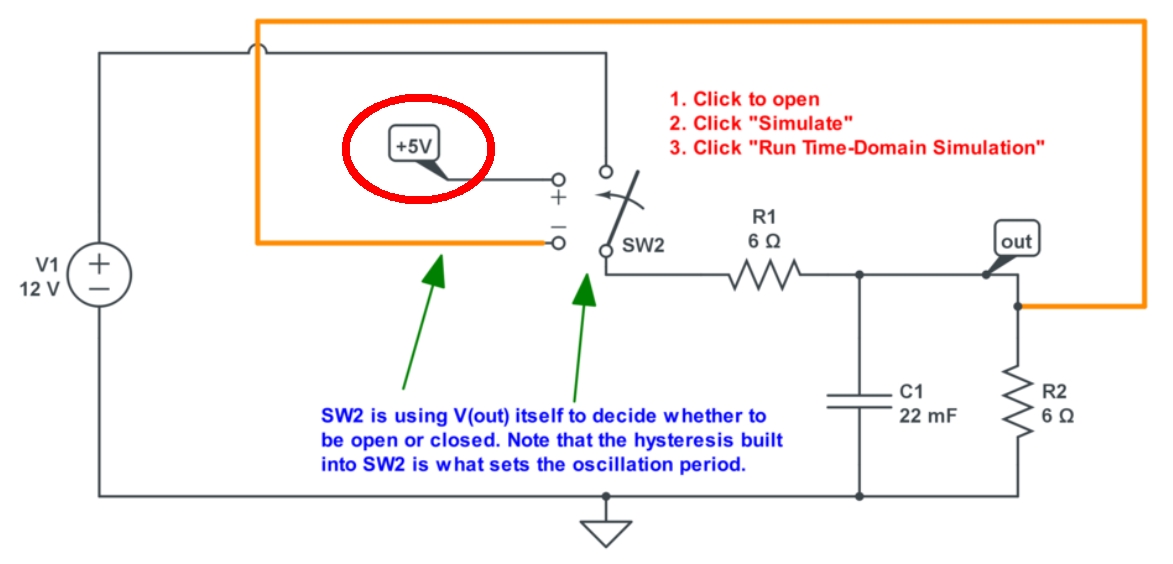
- Finally, we can use a voltage within the circuit itself as the trigger. This example is a bit more complicated, but it uses the fact that the voltage-controlled switch model has hysteresis. Hysteresis means that after the switch changes from one state to the other, there’s some memory so that a larger wiggle is required to get it to switch back to the first state. This is configured within the V_H parameter of the switch SW2. Double-click SW2, try changing the hysteresis voltage V_H, and re-run the simulation:
with a link to these interactive schematics:
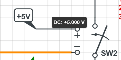
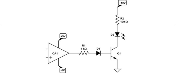
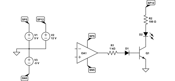
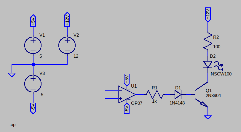
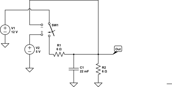
Within this schematic there is a strange node label “+5V” (a “Named node” by the CircuitLab terminology) which I've circled in red. While hovering the mouse over this node, CircuitLab shows that this node's DC voltage is indeed +5 V (shown below), even though it's never connected to a voltage source elsewhere in the schematic.
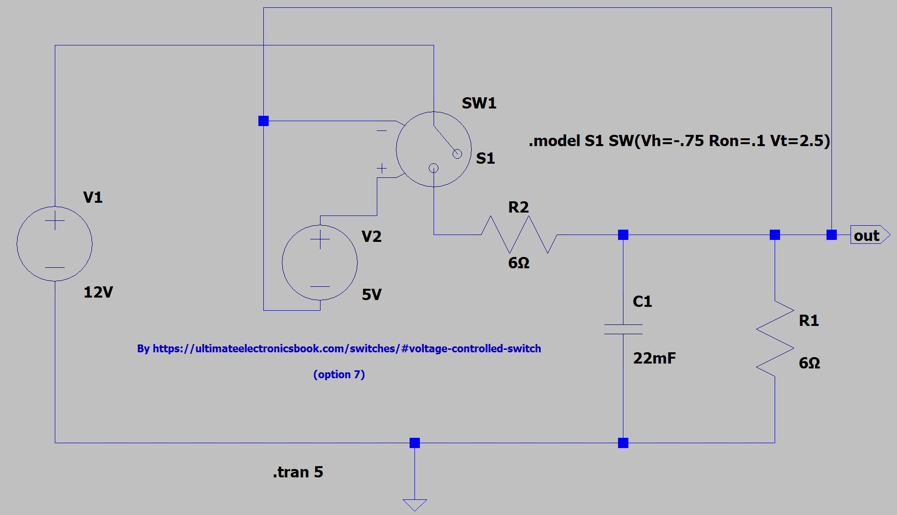
When converting these schematics to LTspice, I decided to replace this "named node" with an explicit voltage source to obtain the same result (for the output voltage value in the time-domain simulation), but without success. I got either a constant value, or the simulation simply didn't work (no window for the waveform viewer; dimmed icon for the “run simulation” symbol). I was forced to halt the simulation with Ctrl + H.
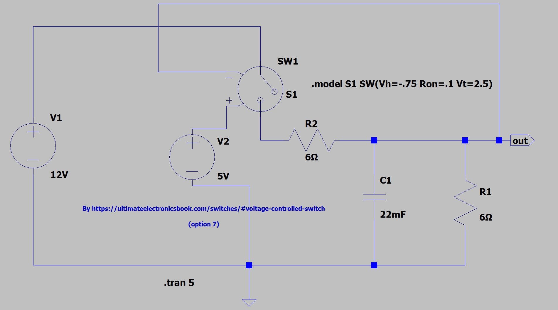
I also tried a different connection of this voltage source (V2), for example this one:
Its netlist (without the first line):
V1 N001 0 12V
C1 out 0 22mF
R1 out 0 6Ω
R2 out N003 6Ω
SW1 N001 N003 N002 out S1
V2 N002 out 5V
.tran 5
.model S1 SW(Vh=-.75 Ron=.1 Vt=2.5)
* By https://ultimateelectronicsbook.com/switches/#voltage-controlled-switch\n\n(option 7)
.backanno
.end
How can I make this work in LTspice (I use version 17.1.14)?
UPDATE:
My question is expressed in its title. I am not interested in other solutions. I want to substitute that strange CircuitLab label (which implies a DC voltage) with something accessible within LTspice.
Why? For any instance in the future where I encounter this same label type in some totally different circuit in CircuitLab.
Here's another thing I tried (the result of its simulation was a constant voltage, about 2.15 V for the “out” node):
UPDATE 2:
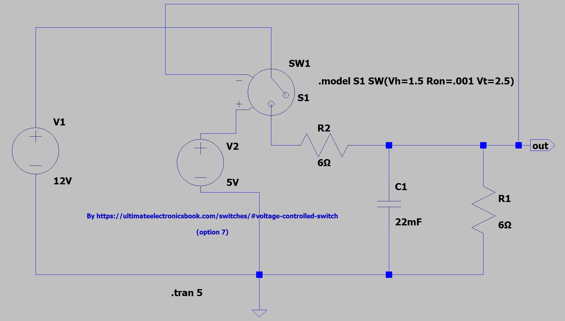
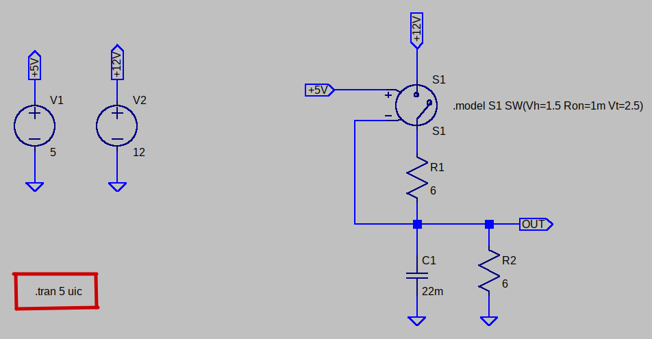
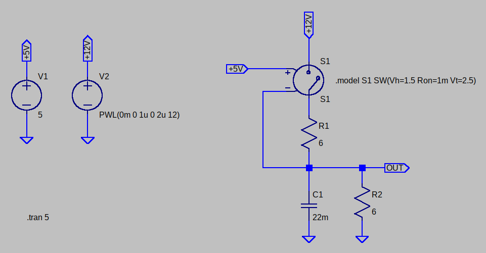
The circuit, which (almost) exactly matches the circuit in CircuitLab, is this one:
The result: no window for the waveform viewer; just a dimmed icon for the “run simulation” symbol. I was forced to halt the simulation with Ctrl + H.
Why almost exactly?
Because:
LTspice doesn't allow zero resistance for a closed switch, so I used 0.001 Ω (1 milliohm) instead.
CircuitLab has only 3 adjustable parameters for a voltage-controlled switch (
R_ON,V_T,V_H), and LTspice has an additional 4 (Roff,Lser,Vser,Ilimit). Namely,Lser(series inductance) andVser(series voltage), both with default values of 0.0, may play some role in the result.


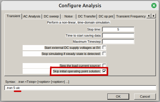
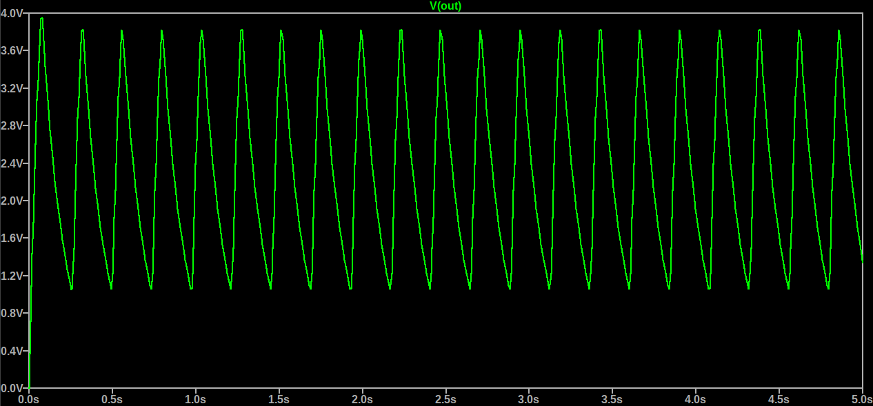
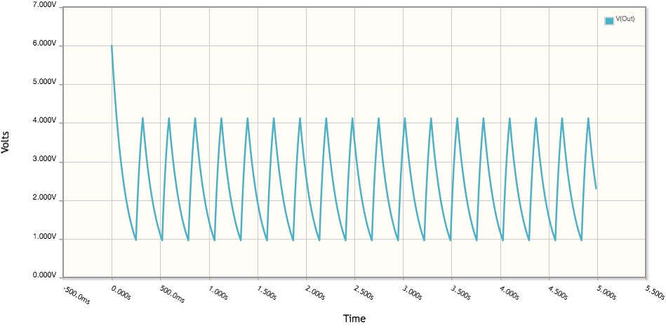
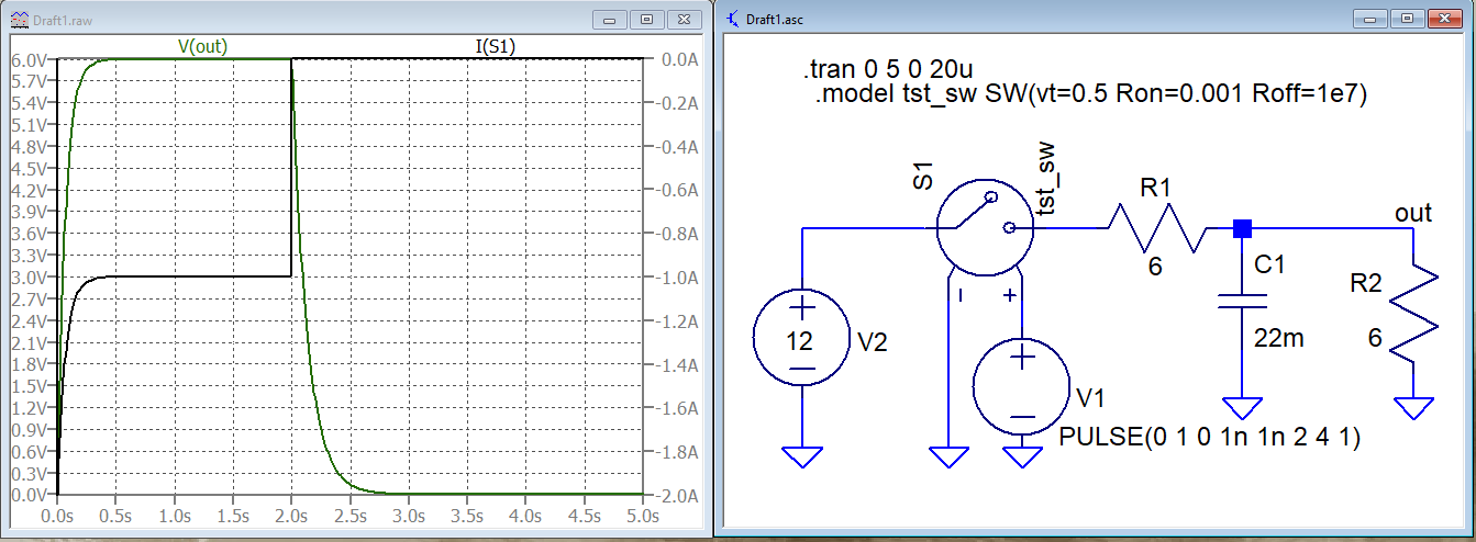
uicparameter was important, the.tran 5 uicwas sufficient. In spite of the waveform is not exactly the same as in CircuitLab (it begins with 0 V instead of 6 V - probably it's related to the initial state of the switch), the shapes are the same. — If you transfer your comment into an answer and explain the importance of theuicparameter, I'll accept it. \$\endgroup\$