4
\$\begingroup\$

I am attempting to monitor DC voltages that can range from 0 to 250V with a micro controller. A simple voltage divider should be suitable for the broad range up to 250V, with somewhat coarse resolution. A second voltage divider for when the voltage is not more than 25V will give me improved resolution at the lower voltage levels. I have no problem using two distinct A/D ports on the micro for each of the dividers. Output of both dividers should be 0 - 5V. I've estimated the values of resistors for the two dividers.
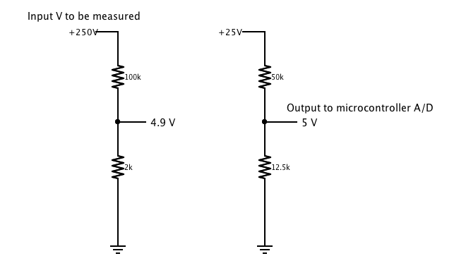
Two voltage dividers for high and low range.

My question is: How can I limit the voltage seen by the second divider so it never exceeds 25V even though it is monitoring the same potential source? I've attempted to utilize a zener in the circuit to clamp the voltage to not exceed 5V but it always seems to effect the linearity of the divider on both the very low end and high end of the ranges. I'm new to designing hardware circuits... as a software guy, I'm really starting to appreciate what's involved in developing analog hardware. Thanks for the help!

\$\endgroup\$

2 Answers 2

3
\$\begingroup\$

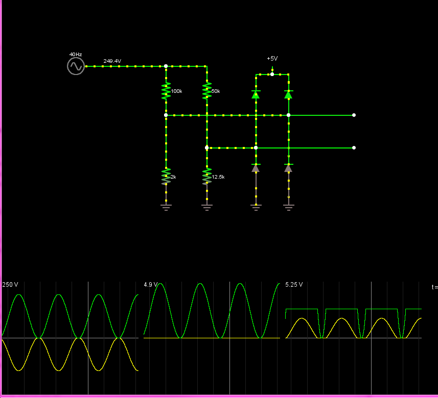
A zener isn't really the answer here, but that doesn't mean diodes aren't the way:

enter image description here

I'm assuming your 5V inputs are going into an ATmega (e.g. arduino) or similar device, where the 5V limit isn't really exactly 5V, but rather "enough above 5V to turn on the protection diodes". In this case, the circuit shown above will work fine.

Caveats are:

  1. Your 5V device needs to be able to sink a ~4.5 mA into the 5V rail (an arduino will do this fine), or the voltage divider will actually cause the 5V rail to increase.

  2. You must use schottky diodes for the diodes. You need your diodes to turn on before the MCU's internal diodes.

  3. The lower two diodes are really extra. They prevent the ADC inputs from going below ground if the input voltage goes below 0V. I don't know if that's a possibility in you application, but it's cheap insurance.

\$\endgroup\$
1
\$\begingroup\$

I don't know what micro you are using but if it were a pic it has a 10-bit ADC so in the high range measurement you have a resolution of 250/1024 which is about 0.25V. There is bound to be a little noise and this will give you a little variation in what you might read from your ADC. If you can take (say) 8 readings and average the result, the noise will help you get a better resolution statistically.

This assumes that the noise is not really slow moving dc drift but ac noise within the nyquist limit of your sampling rate.

So, take as many readings as you can and average them - you'll probably get a resolution that is significantly better than 0.25V and you might find that you don't need to have the lower range voltage divider on another ADC at all.

This technique is called dithering and here is a good article. Here's another and here is wiki's offering.

If you are intent on having two ranges then I'd advise you not to use a zener to protect your input but rather add a x10 gain stage op-amp circuit to the existing sense point in the original voltage divider and feed the output into your 2nd ADC. I don't know what supply rails you have but assuming 5V and 0V you can pick a rail-to-rail op-amp that will do the job like an AD8605.

If you can reduce the ADC's reference voltage by an amount this will also give you some increase in resolution because full-scale will be reduced from 5V to (say) 1V. There are 16-bit ADCs that do this but you may find your micro's ADC doesn't have that facility.

BTW the zener diode idea is not good because it will start conducting significantly belwo the so-called zener voltage and I suspect this is what you are seeing.

\$\endgroup\$
6
  • \$\begingroup\$ Thanks for the response. I'm using an arduino with the ATmega328 micro. Yes, it is 10-bit resolution. I had already implemented an averaging procedure using 16 and 32 sample arrays and it did indeed help with the inherent noise. I'd still like to see better resolution in the low voltage range. Inexpensive multimeters seem to do this when selecting measurement scale. If I select a 20 volt DC scale, the meter simply indicates an error if a 100V potential is attempted. \$\endgroup\$
    – Tim Martin
    Commented Oct 9, 2013 at 15:04
  • \$\begingroup\$ @TimMartin OK then I'd use an op-amp with gain of ten tied to the same voltage divider. Op-amp feeds spare input and there should be no problem. AD8605/6 is my recommendation for a good rail-to-rail workhorse op-amp but there are several that will do and there's probably some very low offset voltage devices that would work really good with extremely low error. \$\endgroup\$
    – Andy aka
    Commented Oct 9, 2013 at 15:12
  • \$\begingroup\$ Thanks for the input Andy. If I understand… the op-amp is used to amplify the lower end of the main voltage divider resulting in a wider range being fed to the second ADC. I'm new to this stuff so I'll look up the data sheet on the AD8605 and then see how to hook it into the circuit. I'm anticipating that the amplification (gain?) is determined by selecting appropriate resistors… and the top-end output of the op-amp is dictated by the rail supply voltage (5V). I guess it's time to dive in again! \$\endgroup\$
    – Tim Martin
    Commented Oct 9, 2013 at 17:47
  • \$\begingroup\$ That's about it in a nutshell. The opamp is configured as non-inverting gain of ten. It also offers protection to the micro. Consider upvoting the answer if you feel it helpful. \$\endgroup\$
    – Andy aka
    Commented Oct 9, 2013 at 17:53
  • \$\begingroup\$ Since I am new, my reputation score is not sufficient to upvote your answer... however your information is indeed helpful. \$\endgroup\$
    – Tim Martin
    Commented Oct 9, 2013 at 23:58

Your Answer

By clicking “Post Your Answer”, you agree to our terms of service and acknowledge you have read our privacy policy.

Not the answer you're looking for? Browse other questions tagged or ask your own question.