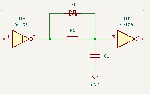
If I was really trying to charge that cap as quickly as possible, I would probably consider spending a couple of cents on an output drive transistor, to make things a bit more predictable and almost certainly faster.
However your phrase "as little delay as possible" leaves me with a feeling of incompleteness. There must be some minimum (1ns? 10ns? 100ns?) which is definitely tolerable and I would begin by trying to define that, otherwise it's rather hard to decide what is or is not a good solution.
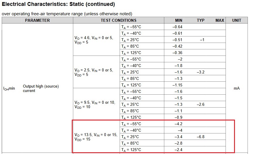
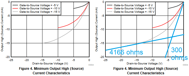
With this kind of situation it also becomes important to know a bit more about your design objectives. Are you making one or ten thousand of these? (This would make me think about how much I trust those graphs of output characteristic to be reliably true for every chip in a big batch.) Is cost of extra parts a big deal (i.e. are you trying to shave every last cent off the cost?)
As I consider this circuit, I realise that there are two parameters at play here - the DELAY through the circuit (which you want to minimise) and the required PULSE WIDTH at the input to charge C fully and thus ensure that the delay is achieved. (A short pulse will cause incomplete charge and thus possibly a reduced delay.)
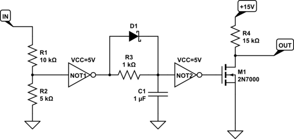
You could add one resistor and limit the charge current into C, while still having the output respond to the input with minimum delay. I think this helps your delay figures (as you now know the output voltage of the first stage will not be stuck low for a short period trying to charge the cap), at the expense of a longer (but well defined) input pulse to charge the cap fully. There is some dependence between pulse width and delay here, you may need to think about that (but there was before as well for very short pulses).
The values given here are notional, R1 sets the delay and R2 sets the minimum pulse width of the input that will cause the delay to take effect. For the values I give, the minimum pulse is around 20uS and the delay is about 0.5s (very approximate), of course you can adjust these to fit your application.
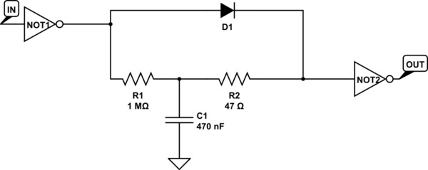
simulate this circuit – Schematic created using CircuitLab

