0
\$\begingroup\$

Let's say I have an NMOS, the gate is connected to 5 volts, Vth is 0.7 volts and I want to pass a voltage of 7 using the NMOS as a switch. Can you tell me what will be the voltage at the source? Will it be 4.3 or 6.3?

In my understanding, once a voltage greater than Vth is applied at the gate, the source and drain are effectively shorted, this means the voltage at the drain should appear at the source.

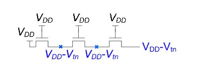
The reason I ask is because of the picture below. The picture suggests, irrespective of what the drain voltage is, the voltage at the source is always the gate voltage minus Vth

enter image description here

\$\endgroup\$

2 Answers 2

2
\$\begingroup\$

The illustration is correct. VGS must be above Vth for the NMOS to be ON, otherwise it will be OFF. Therefore in your circuit the maximum possible voltage at the source is VDD-Vth, otherwise the NMOS would be OFF. Note that in your circuit VGS=VDD-(VDD-Vth)=Vth, so it is ON, but the voltage at the source cannot increase further because it would turn OFF the NMOS (and the source voltage would decrease, turning it ON again). It therefore comes to an equilibrium where VGS=Vth.

The fact that there is three NMOS instead of one doesn't change this situation, because all 3 NMOS have the same VGS voltage.

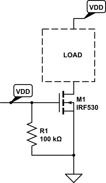
If you want to use an NMOS as a switch and have the full VDD on the load you should place it in the low side as in the following picture.

schematic

simulate this circuit – Schematic created using CircuitLab

\$\endgroup\$
1
  • \$\begingroup\$ Of course you can high-side switch a load with a PMOS (p-channel) device. Also the OP's picture is missing the body connections, although it makes no difference in this situation, it's always good to know what the back-gate or body is doing. \$\endgroup\$
    – jherbold
    Commented May 17, 2017 at 18:56
0
\$\begingroup\$

Quick answer - a FET is not a bipolar transistor.

Vth relates to the minimum voltage present between Gate and Source: Vgs(threshold) if you like. The voltage present at the source will depend on the resistance between source and drain for that particular Vgs.

For an N FET, the diagram you have will not work. If the Source voltage approached the Drain voltage and the Gate voltage is also the Drain voltage, then Vgs -> 0. You need a P FET and you need the Gate to be closer to 0V.

Edit: This was an overly hasty answer patched with edits but I'll leave them as they are as Roger's comments on my answer and edits hold more value. The edits I made are:

1) Roger C's answer assumes something I didn't - that the voltage on the right (Vdd - Vth) is being held at that potential by an external reference. In that case, the illustration is correct (the maximum possible voltage at the source is VDD-Vth, otherwise the NMOS would be OFF).

2) The OP said "The picture suggests, irrespective of what the drain voltage is, the voltage at the source is always the gate voltage minus Vth". Your understanding of cause and effect is backwards: The voltage at the gate must be the voltage at the source plus a minimum of Vth in order for the NFET to be on.
\$\endgroup\$
9
  • 1
    \$\begingroup\$ Field Effect Transistor is not a transistor?!!! \$\endgroup\$
    – nidhin
    Commented Apr 4, 2015 at 12:11
  • \$\begingroup\$ @nidhin: Doh! I need more sleep. Editing post. \$\endgroup\$
    – carveone
    Commented Apr 4, 2015 at 12:13
  • \$\begingroup\$ Actually, I'm not assuming that the voltage at the right is being held by an external reference. On the contrary, I assume that the load is passive. The voltage at the right comes from the left, but it cannot be above VDD-Vth. \$\endgroup\$
    – Roger C.
    Commented Apr 4, 2015 at 12:18
  • \$\begingroup\$ @RogerC. Ah I see. My initial impulse was that if the load was passive, the voltage at the right would rise to Vdd. Which would switch the FETs off which would, um, cause the voltage to fall to 0 which would... Er. Ok, I'm evidently having a senior-moment-morning :-) \$\endgroup\$
    – carveone
    Commented Apr 4, 2015 at 12:22
  • \$\begingroup\$ @carveone So the first part of the question, the voltage will be 6.3 right? \$\endgroup\$
    – Sidd
    Commented Apr 4, 2015 at 12:23

Your Answer

By clicking “Post Your Answer”, you agree to our terms of service and acknowledge you have read our privacy policy.

Not the answer you're looking for? Browse other questions tagged or ask your own question.