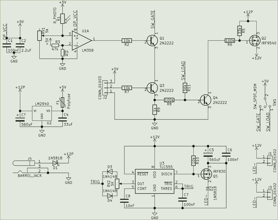
Based on the well-known Inventable.eu article, I combined their CMOS timer PWM with adjustable duty cycle with logic that switches the supply to the timer circuit. Only when the gate conditions (AND; both signals are true) are satisfied is 12V supplied to the rest of the circuit.
The following image represents the circuit I have built:
My problem is achieving a ramp down effect when the 12V supply to the timer sub-circuit is shut off. My first attempt was an RC network at the base of Q4, but this only delayed the switch off and did not produce the desired fade out effect. For my second test, I added a 1000uF capacitor in parallel with the 560uF listed in the schematic. The resulting delay was too short.
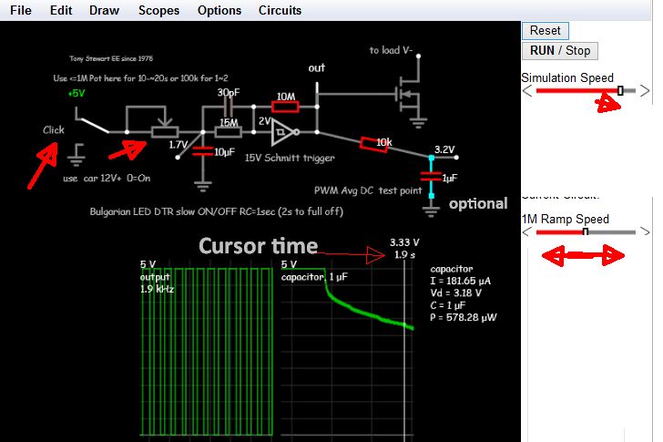
My question: how to introduce a delay without compromising the pulse switching Q5. One possible solution is outlined here, but I am unsure how this could be adapted, and want some other options before salvaging the necessary opto isolator device.
Can you please explain in your answer how your solution interacts with the timer's PWM and the rest of the circuit, particularly the high side switching at Q2. Thank you.
Update: based on Mr. Tony Stewart's comments, it appears my design may simply be incompatible with any sort of off-ramp. While there are perhaps options involving the 555's reset in place of the high side switch, I prefer keeping it as-is, if only for the lower current consumption.


