1
\$\begingroup\$

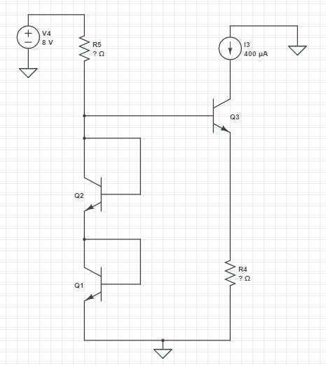
In this schematic \$ V_{BE(on)} = 0.7 V \$, \$ \beta=100 \$ and \$ R5, R4 \$ are unknown. After calculations I find that \$ R4 = 1.75kΩ \$ and \$ R5 =16.5kΩ \$ but I am not sure for these results. What is the right answer?

Can anyone help me if transistor \$ Q3, Q2 \$ act as a current mirror?

Circuit

\$\endgroup\$
5
  • \$\begingroup\$ No Shockley equation ? And the BJT's are identical ? \$\endgroup\$
    – G36
    Commented Apr 30, 2017 at 11:07
  • \$\begingroup\$ Ie3 = Ic3+Ib3 = (beta +1)/beta * Ic3 = 404uA so R4 = 0.7V/404uA = 17.326kΩ. IR5 = Ib3 + (Ic2+Ib2) = Ib3 + Ie2 = Ib3 + 50Ib3 = 204uA--->R5 = (8V - 1.4V)/204uA = 32.352kΩ \$\endgroup\$
    – G36
    Commented Apr 30, 2017 at 11:33
  • \$\begingroup\$ G36 thank you for your answer.Indeed BJT's are identical.However, your equation R4 = 0.7V/404uA I think it's wrong because emmiter voltage of Q3 it isn't O.7V but 1.4V.Also I don't understand why Ie2 =50Ib3 as you mentioned above.Thank you \$\endgroup\$
    – elecV1
    Commented Apr 30, 2017 at 11:50
  • \$\begingroup\$ The Q3 emitter voltage is: Ve = Vb3 - Vbe3 = Vbe1+Vbe2 -Vbe3 = 0.7V + 0.7V - 0.7V = 0.7V. As for why Ie2 = Ib3 + 50Ib3 the Ie2 current should be much larger then Ib3 so I assumed 50 times larger. \$\endgroup\$
    – G36
    Commented Apr 30, 2017 at 11:58
  • \$\begingroup\$ Thanks again G36.You are right for VE1=0.7V I was confused.For your second thought I believe it's a good explanation but maybe there are another solution without assumptions. \$\endgroup\$
    – elecV1
    Commented Apr 30, 2017 at 12:09

1 Answer 1

1
\$\begingroup\$

If you assume that Vbe = 0.7v (not too far wrong with no other information), then you have R4 correctly calculated at 1.75k.

R5 is a different story. That's not a current mirror circuit. R5 can be anything from very small to quite large. If 'act as a current mirror' means we chose the Q1/R5 current be 400uA as well, then making the same 0.7 assumption leads to an R5 of (8-1.4)/400u = 16.5k.

If Q1 were replaced by a 1.75k resistor, that would be a current mirror, and changes in the current through R5 would be faithfully reflected to the output I3. As the voltage across Q1 varies little with changes in current, R5 could go up or down by a factor of 10 with very little change in the output current.

\$\endgroup\$
1
  • \$\begingroup\$ G36 thank you for your answer.Indeed BJT's are identical.Also beta=100,VBEon=0.7V,Vτ=25mV for all transistors..I think that VE1=0V,VB1=VC1=VE2=0.7V, VB2=VC2=VB3=1.4V and for calculate R5 I know that IR5 = (8-1.4 )/R5 and the only unknown variables is IR5.If I assume that IC3 = IR5 because of Q2,Q3 is current mirror then I can find the solution because IR5=400uA so R5 = (8-1.4 )/400uA.HoweverI am not sure for these thoughts. \$\endgroup\$
    – elecV1
    Commented Apr 30, 2017 at 12:01

Your Answer

By clicking “Post Your Answer”, you agree to our terms of service and acknowledge you have read our privacy policy.

Not the answer you're looking for? Browse other questions tagged or ask your own question.