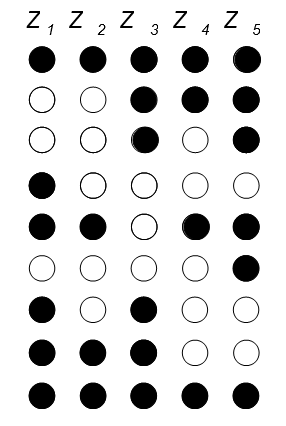
The idea here is to design a circuit that goes from one state to the next (line of Z_i values) on a clock edge or possibly clock edge plus enable input.
This is typically a Moore machine: all outputs only depend on your state variables. When building a Moore machine, you have to decide on your internal representation as well as how to decode your internal representation to your output values. This means, you will have to create both a) transition logic between states and b) output decode logic.
You can also build a special form of Moore machine called a Medvedev machine. It's a Moore machine where internal state and output coincide, i.e. they are the same.
Starting with a binary counter can be useful if you have the luxury of using a look-up table (LUT), where you provide an address into a piece of memory that outputs as many bits as you need in parallel. For hand-coding, it might not be the best starting point.
To find a proper encoding for your internal state, you would typically look at your output values and devise a clever way to reduce it. Find duplicate bits (groups of bits that are always the same per state), find symmetries, etc.
In your case, one thing that's immediately obvious is the symmetry in your states.
11111
00111
00101
10000
11011 <-- point of symmetry
00001
10100
11100
11111
Immediately, this means that you can use one bit in your internal representation to just switch all outputs around. Your pattern has a circular nature, so something like a Johnson counter comes to mind:
state output
state output
0000    11111
1000    00111
1100    00101
1110    10000
1111    11011
0111    00001
0011    10100
0001    11100
0000    11111
Notice how the Johnson counter transition is very simple, it's simply shift every bit right, take right-most state bit, invert, shift into first state bit: s2' <= s3; s1' <= s2; s0' <= s1; s3' <= not s0;
Make right-most Johnson counter bit switch state bit and output bit orders:
state   state    output   output
       switched          switched
0000    0000     11111    11111
1000    1000     00111    00111
1100    1100     00101    00101
1110    1110     10000    10000
1111    1111     11011    11011
0111    1110     10000    00001
0011    1100     00101    10100
0001    1000     00111    11100
0000    0000     11111    11111
Notice how the inversion reduces your state space:
 state    outputs
switched
 0000      11111
 1000      00111
 1100      00101
 1110      10000
 1111      11011
You will have to do the switching yourself using multiplexer-style logic q0' <= (s0 and q4) or (not s0 and q0) etc. Same for switched state inputs to your output logic: v0 <= (s0 and s3) or (not s0 and s0) etc.
You can now use Karnaugh maps to simplify your expressions. Then plug the multiplexer equations into your output logic expressions and you should be done.
Notice how this is one possibility. You could use a binary counter, you could use random states to get started etc.
For instance, logically, since none of your lines are the same, you technically only need ld(#states) bits to encode the information. This has the advantage of saving one flip flop. The disadvantage being that you have to devise state transition logic as well as output decode logic now.

