2
\$\begingroup\$

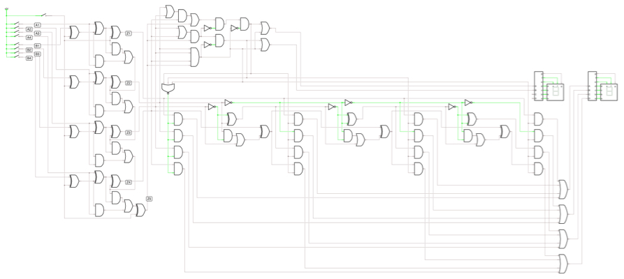
I'm making an Arithmetic Logic Unit(ALU) for an assignment and I'm on a point. So according to my circuit design on the link shared below, I am able to output 1 digit of my alu. It is a 4 bit ALU so the maximum output can be a result of an addition i.e. 9+9 = 18. This is where my problem is.

The correct output is shown until 9 on the 7 segment display. After that, random gibberish is shown. I added LEDs to see the binary output to check if the correct output is received in my simulation. Since there are only 4 bits, the output on LEDs also goes maximum to 1111 (for output 15 in decimal). After that it is reset to 0000 for 16 and starts all over again.

Can anyone please guide me with the correct approach to take here? How can I make 2 7 segment displays show my correct output in decimal? so that until the output is less than 9, the first 7 segment shows zero, but as soon as the output goes to 10, the first 7 segment displays a 1.

Help is much appreciated.

View post on imgur.com

\$\endgroup\$
13
  • \$\begingroup\$ Easier to use an LED driver that can display a hex digit. Otherwise you have to do a conversion to decimal. \$\endgroup\$
    – stark
    Commented Apr 24, 2016 at 11:11
  • \$\begingroup\$ I have some idea that I have to use a BCD to 7 segment decoder. I'm already using that to display the one digit. How to extend it to display on 2 separate displays? \$\endgroup\$
    – Ching Ling
    Commented Apr 24, 2016 at 11:14
  • \$\begingroup\$ Also I'm not sure we're allowed to use hex digits. Would be better if I find a solution to convert to decimal from binary. \$\endgroup\$
    – Ching Ling
    Commented Apr 24, 2016 at 11:16
  • \$\begingroup\$ You can write C or assembly that turns on and off individual bits of the seven segment displays. The input to the function can be the number, and the code set the bits for the displays. \$\endgroup\$ Commented Apr 24, 2016 at 11:24
  • 1
    \$\begingroup\$ If you are doing everything in decimal then you should change the logic of your adder to carry at 10 and generate the correct digit output. \$\endgroup\$
    – stark
    Commented Apr 24, 2016 at 11:25

1 Answer 1

1
\$\begingroup\$

This circuit could be simpler, but it achieves what you want without modifying your original circuit.

Complex circuit

https://i.sstatic.net/dTrrU.jpg is the link to the photo so you can zoom in for better detail.

\$\endgroup\$
2
  • \$\begingroup\$ Am I correct in assuming you added \$x\ge10\$ and \$x-10\$-logic to the circuit? \$\endgroup\$ Commented Apr 28, 2016 at 19:18
  • \$\begingroup\$ Sorry but unfortunately I haven't learnt the notation for writing logic using text. If you send me a link, I could learn it quickly. \$\endgroup\$
    – Bradman175
    Commented Apr 28, 2016 at 23:39

Your Answer

By clicking “Post Your Answer”, you agree to our terms of service and acknowledge you have read our privacy policy.

Not the answer you're looking for? Browse other questions tagged or ask your own question.