0
\$\begingroup\$

I have a differential clock signal coming from an IC. If the signal is present, I need a TTL "high" to enable a high-side FET driver. When certain conditions are violated, the IC will send the differential signal to ground which will disable the driver and the FET will turn off.

The issue is turning the clock signal into a logic high and also getting a logic low when the signal is sent to ground. I had the thought of comparing the output signal with the clock through a differential amplifier, but I feel that might be too susceptible to noise - especially considering the application is for an electric vehicle. Is there an easier way to do this?

Tl;dr: I need a logic high if the clock is present and a logic low if it is not.

\$\endgroup\$
4
  • 3
    \$\begingroup\$ You need to specify the frequency, the time-out, what happens if clock freezes high and what happens if it freezes low. \$\endgroup\$
    – Transistor
    Commented Aug 28, 2016 at 22:23
  • \$\begingroup\$ Is the differential clock already clean digital signals? The first part of the problem might be as simple as putting the signals into an exclusive-or, XOR, gate. Then continuously trigger something to hold the output signal across clock transitions. So you need to answer Transistors questions to get complete answers. \$\endgroup\$
    – gbulmer
    Commented Aug 28, 2016 at 22:38
  • \$\begingroup\$ What do you mean by 'differential' clock signal, and how does it get 'sent to ground'? \$\endgroup\$ Commented Aug 28, 2016 at 23:53
  • 1
    \$\begingroup\$ You need a retriggerable one shot \$\endgroup\$ Commented Aug 29, 2016 at 0:12

1 Answer 1

2
\$\begingroup\$

Taking the TLDR at its words, "I need a logic high if the clock is present and a logic low if it is not":

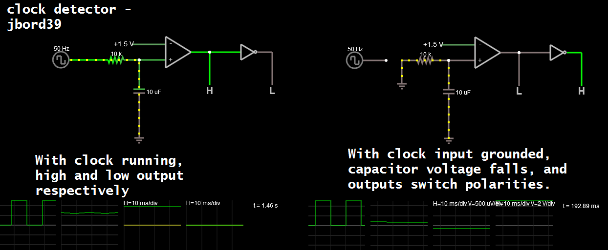
Send the clock into a low pass filter. It should have a voltage of half the maximum clock voltage (assuming 50% duty cycle) when the clock is running. When the clock cuts out this will drop to 0V. Feed this into a comparator at like 1/4 of the supply voltage (tweak this value for drop-out time). One more inverter and you have both polarities.

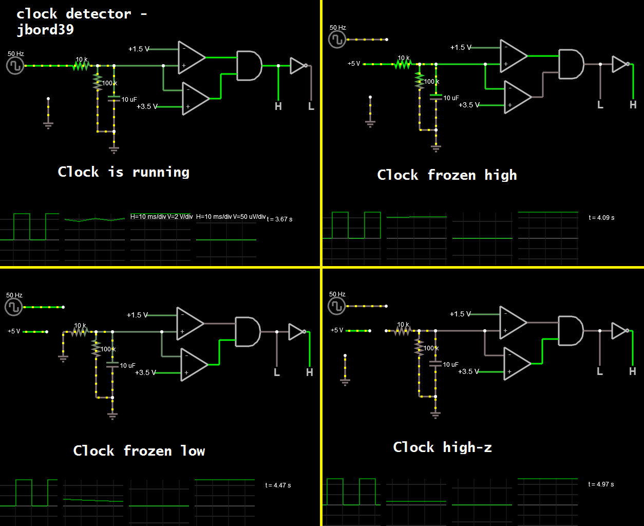
I am assuming that this "When certain conditions are violated, the IC will send the differential signal to ground which will disable the driver and the FET will turn off." means the clock won't freeze high. If it does, this circuit wouldn't work properly without some tweaking (just brainstorming, you could add another op-amp, this time comparing to 4/5 of the supply voltage; which would check for a frozen clock at high logic w/ an AND, will update post).

The simulation is shown below. Add more sophistication as needed I suppose:

clock detector

Just in case the clock could freeze high, here is a modification which checks for the clock frozen at either low or high (and w/ a bleeder resistor in case clock goes high-z):

updated for other conditions

\$\endgroup\$
7
  • \$\begingroup\$ How would a low pass filter rectify the voltage to roughly half of the max voltage? Doesn't the low pass filter just pass lower frequencies? \$\endgroup\$
    – Daniel
    Commented Aug 28, 2016 at 23:41
  • \$\begingroup\$ @Daniel: A passive filter is also a voltage divider. You are able to compute frequency dependent impedances, yes? \$\endgroup\$
    – jonk
    Commented Aug 28, 2016 at 23:49
  • 1
    \$\begingroup\$ @Daniel: Yes, it does pass the low frequencies (DC is the lowest frequency of 0 Hz or radians). You make the low-pass filter have a cutoff frequency below your input clock. A clock which is 0-5V has an average DC value of 2.5V; if the duty cycle changes the avg DC value will also change. This is basically frequency of 0 on the Laplace or Fourier transform. Since this is below the cutoff frequency of the low-pass filter (it is 0 Hz), it shows up at the output. \$\endgroup\$
    – jbord39
    Commented Aug 28, 2016 at 23:52
  • \$\begingroup\$ @jbord39 I think I understand what you are saying...So basically I want a low pass filter which will only pass DC (0 Hz) which would pass the avg DC value. That avg value depends on the duty cycle but a 50% duty cycle with a 0-5V clock would result in 2.5V out of the low pass filter. Is that correct? \$\endgroup\$
    – Daniel
    Commented Aug 29, 2016 at 0:10
  • 1
    \$\begingroup\$ @Daniel: Falstad circuit simulator. Yes, it is amazing. It runs in real-time, in-browser, for free. It is perfect for just prototyping simple stuff. \$\endgroup\$
    – jbord39
    Commented Aug 29, 2016 at 1:19

Your Answer

By clicking “Post Your Answer”, you agree to our terms of service and acknowledge you have read our privacy policy.

Not the answer you're looking for? Browse other questions tagged or ask your own question.