0
\$\begingroup\$

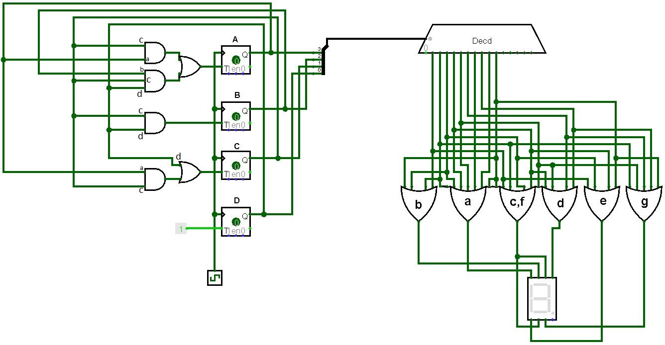
I have 2 7473 (JK-FF) ICs. So there are a total of 4 flip-flops with 4 clock inputs. They will all have the same clock pulse (check attached simulation screenshot).

I'm using a 555 timer IC to send the clock pulse. My question is can I just short the clock pins on the 7473 ICs and connect them to pin-3 of the 555 IC, using wires? Or do I need to use resistors to short them?

enter image description here

\$\endgroup\$

2 Answers 2

1
\$\begingroup\$

Inputs can be connected together, usually at least 10 are okay when driven from a logic output in the same family.

They should be connected to exactly 1 output (or to something such as a pullup resistor which simulates an output).

The LM555 (bipolar version) is advertised as being TTL-compatible. It is guaranteed to have less than 350mV drop when sinking 5mA with a 5V supply. Each standard TTL input is 1.6mA so it can drive as many 3 inputs with more than 400mV of noise immunity (800mV or less is recognized as a 0 by the flip-flop).

enter image description here

A fan-out of four will almost surely work okay for a hobby project. If you want to be really sure, drive a single TTL gate input with the 555 and use the output of the gate to drive the clock inputs.

Do not put resistors in series with TTL inputs. The resistors will harm the noise immunity when at logic '0' or may even keep the input from being recognized as a '0'. Sometimes you will see low value (some tens of ohms) resistors in series with clock signals to help tame ringing but a 555 is rather sluggish (100ns rise/fall times) so I doubt that will be an issue.

\$\endgroup\$
4
  • \$\begingroup\$ And what if I want to do manual clock pulses? Can I do the same, except use Vcc instead of pin-3 of the 555? \$\endgroup\$ Commented Nov 25, 2016 at 19:40
  • \$\begingroup\$ If you want to do manual clock pulses with a switch (and have it behave sensibly) you must build a debouncing circuit. One of the simplest is 1/2 a 7400 and a SPDT switch with two pullup resistors. You could also use the 555 itself, but that's beyond the scope of this comment or indeed the question. \$\endgroup\$ Commented Nov 25, 2016 at 19:50
  • \$\begingroup\$ See the problem is, I'm new to the 555 and I'm not sure how to set it up for this circuit. I've looked at some of the projects on the 555 website, and I'm not sure what capacitance/resistance to use. So I just wanted a way to test whether my sequential circuit works, by providing the pulse manually. \$\endgroup\$ Commented Nov 25, 2016 at 20:00
  • \$\begingroup\$ Search for debounce circuit. electronics-tutorials.ws/io/io80.gif?x98918 \$\endgroup\$ Commented Nov 25, 2016 at 20:02
0
\$\begingroup\$

In most digital logic circuits parts can be connected directly, with no extra components.

It is very common to drive several inputs from a single source, with no extra resistors between the inputs.

\$\endgroup\$

Your Answer

By clicking “Post Your Answer”, you agree to our terms of service and acknowledge you have read our privacy policy.

Not the answer you're looking for? Browse other questions tagged or ask your own question.