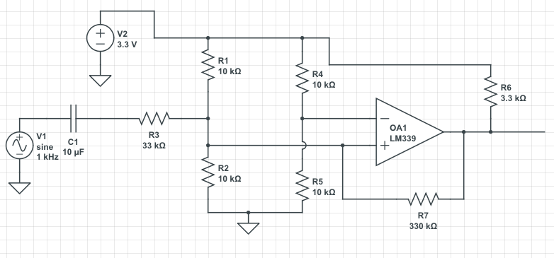
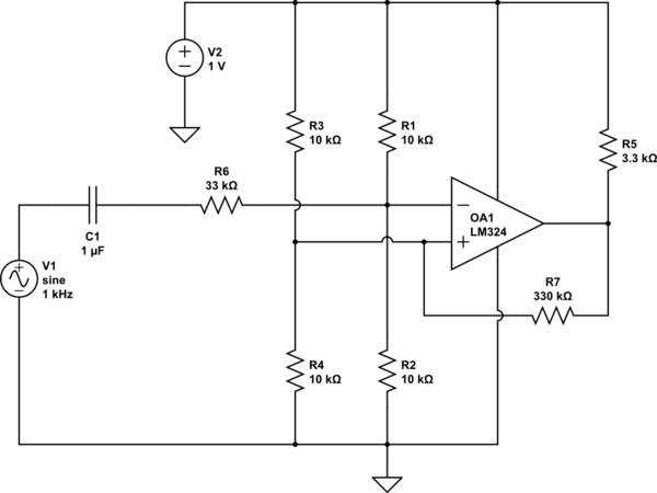
I'm trying to simulate the circuit posted here, which looks like this:
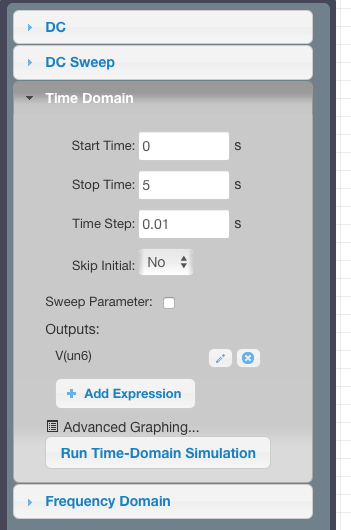
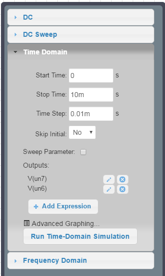
I'm running a transient analysis and have the following settings:
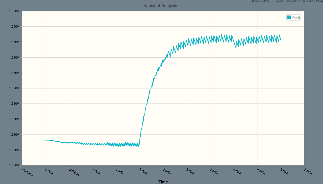
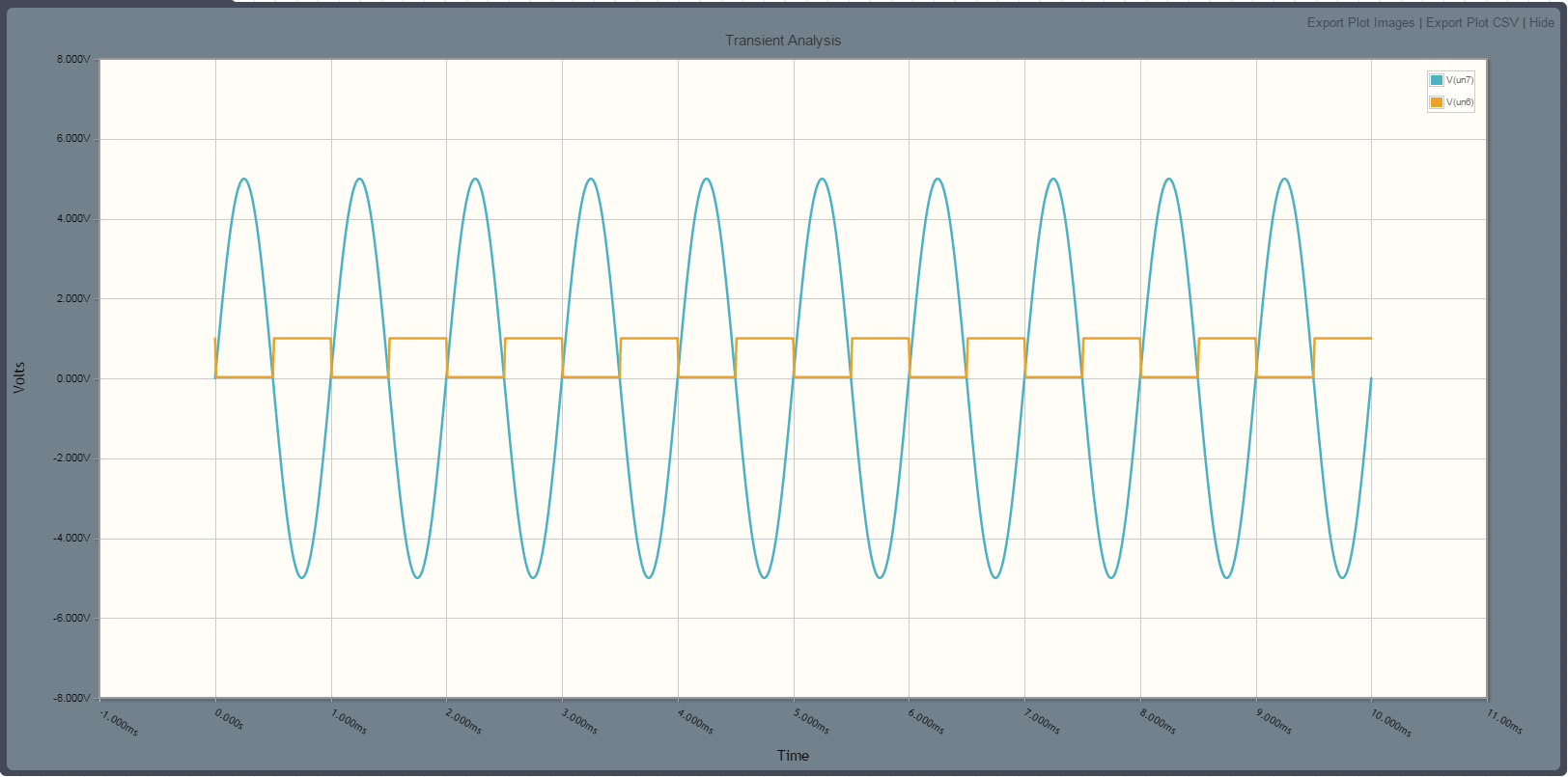
I expected to get the output as a square wave, but I'm getting this instead:
Does anyone know why I might be getting a zigzag wave rather than a square wave?
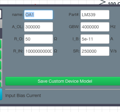
Here is the definition of LM339 used:
EDIT:
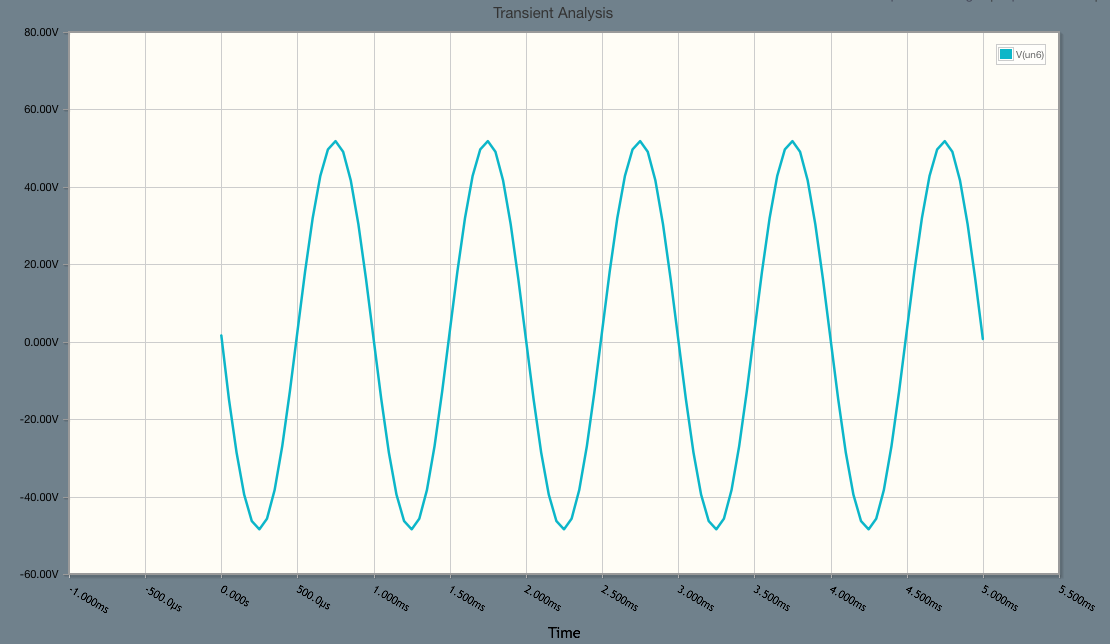
If I use a time step of 0.055ms and the stop time to just 5ms, I get the following:
which is still not a square wave.
The amplitude of the input signal is 5V.

