0
\$\begingroup\$

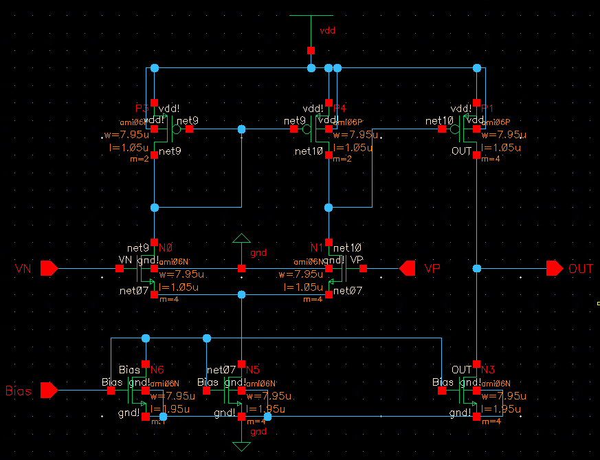
I am trying to simulate the following cmos comparator circuit using cadence virtuoso spectre.enter image description here
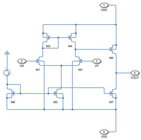
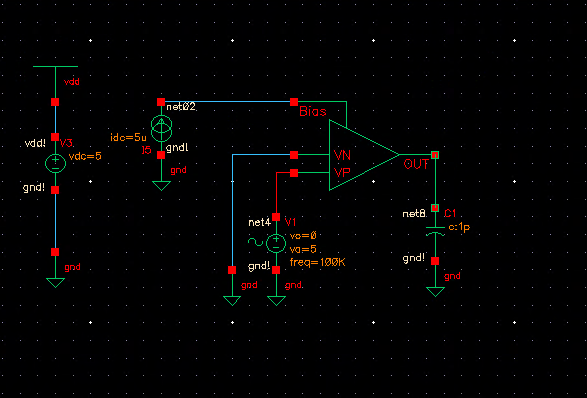
Here's my schematic on cadence: enter image description here I am using the following test bench to simulate the circuit with Ibias = 5 microAmp, VDD = 5 V, VSS = 0. VN is grounded and VP is a sinewave.

enter image description here

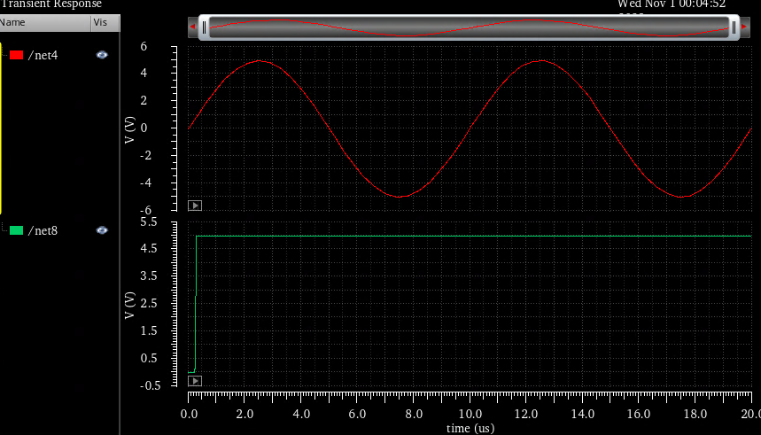
This is the result of transient simulation. As can be seen the output on the bottom does not react to the input at all. I expected to see a square wave but I just get Vdd the entire time. Any feedback on this?enter image description here
\$\endgroup\$

1 Answer 1

0
\$\begingroup\$

You have not biased the comparator properly. An NMOS input pair comparator will need the reference voltage to be higher than VGS(M1)+VDS(M5). Since you've connected the reference to 0V, the comparator will not work.

To get this to work, you need to figure out a value of VGS(M1)+VDS(M5) such that the transistors are all in saturation. Then, you can feed this as your comparator reference voltage. You can then feed a 0-5V sine wave on the other comparator terminal.

\$\endgroup\$
2
  • \$\begingroup\$ Your suggestion worked. I had to change reference voltage from 0 to a value such that the M1 is saturated. If I were insistent on having 0 V as the reference voltage, how should I modify the circuit? \$\endgroup\$
    – ah286
    Commented Nov 1, 2023 at 5:31
  • \$\begingroup\$ You could try a pmos input pair based comparator. \$\endgroup\$
    – sai
    Commented Nov 1, 2023 at 6:35

Your Answer

By clicking “Post Your Answer”, you agree to our terms of service and acknowledge you have read our privacy policy.

Not the answer you're looking for? Browse other questions tagged or ask your own question.